Invented by Lee; Young Jin, Graybill; Scott, Fonken; Matthew, Dhital; Ashish, Lawver; Jordan, Kahle; Kent, Khare; Vinod, Trimble Inc.
Surveying is all about finding out where things are. But what happens when your surveying pole, or rover, isn’t perfectly straight? This is where tilt-compensation surveying comes in. In this article, we’ll go step by step through the background and need for this invention, look at the science and older solutions, and then break down how this new system works and why it’s so special. By the end, you’ll see how surveying can be made much simpler and more accurate, even when things aren’t perfectly level.
Background and Market Context
Surveying is everywhere in our lives. Think of building a house, laying out a park, or checking where a road should go. Surveyors, builders, and engineers need to know exactly where points are on the ground, walls, or ceilings. Traditionally, this means using special tools—surveying rods, total stations, and sometimes fancy headsets with cameras. The goal is always the same: get the location right, down to the last millimeter, no matter how tricky the job site.
But job sites are rarely perfect. Sometimes you need to measure a point that’s hard to reach, like the corner of a wall or the top of a ceiling. Maybe the ground is bumpy, or there’s something in the way. In these cases, you might have to tilt your surveying rod. But when you tilt the rod, the old way of measuring falls apart. The standard method assumes the rod is straight up and down, but if it’s at an angle, the point you’re measuring can be off by several centimeters or more. This can lead to mistakes, extra work, and lost time.
The need for a better, simpler way to measure accurately—even when the rod is not straight—has been growing for years. Construction sites are getting busier. There’s a push for faster work and smaller teams. Sometimes workers don’t have years of experience, so tools need to be easy to use. Plus, new technology like augmented reality (AR) headsets are finding their way onto job sites, promising smarter ways to see and record where things are.
Existing tools are expensive and require lots of training. Using a total station (a device that shoots laser beams to a reflector on the rod) or a head-mounted display with cameras means carrying extra gear and learning new skills. Many smaller firms or projects just want a way to measure quickly and correctly, without extra hassle.
Tilt-compensation surveying aims to answer this need. It lets anyone measure accurate points, even if the tool is tilted, by using a mix of a rover (like a pole or robot), a separate surveying device (like a total station), and smart software that knows the relation between parts of the rover. This is a big leap forward for the industry and opens the door for more people to work faster and make fewer mistakes.

Scientific Rationale and Prior Art
To understand why this invention matters, it helps to know how things worked before. Traditional surveying works best when everything is straight. The rod is supposed to be vertical, the reflector at the top points back to the total station, and the distance from the tip (which touches the ground or a surface) to the reflector is known. The total station shoots a laser, measures the distance, and calculates the position. If the rod is perfectly upright, this works great.
But as soon as you tilt the rod, the math falls apart. The distance from the reflector to the tip is no longer just a simple vertical line—it becomes a diagonal, and the tip is not directly under the reflector. This creates errors in measurement. Surveyors have to keep the rod level, sometimes using bubble levels or extra sensors, which slows things down and makes measuring in hard-to-reach places almost impossible.
Some older solutions tried to solve this by adding more sensors. For example, you could put two reflectors on the rod, and have the total station track both. If you know exactly where both reflectors are, you can figure out the tilt and calculate the real position of the tip. But this method gets complex and expensive. Sometimes, inertial sensors (IMUs) are added to the rod to measure tilt, but these can drift, get confused by sudden movement, or need frequent calibration.
Another approach uses cameras and computer vision. Augmented reality headsets, like Microsoft’s HoloLens or Trimble’s XR10, can build a digital map of the area and help track the position of tools and people. But these systems can drift as you move, meaning the digital map slowly becomes less accurate compared to the real world. To fix this, visual markers like QR codes can be placed around the site, and the headset looks at them to “snap back” to the right location. But setting up lots of markers is a pain, and you still need to measure them all accurately with the total station.
Some prior systems tried to use a single visual marker attached to the rod, but without a good way to connect the camera’s measurement to the total station’s laser measurement, the results were not precise. Others used robots or vehicles as mobile rovers, but these too had trouble when the ground was not even or the robot tilted as it moved.
The main issues with all these old approaches are:
– They require lots of extra equipment (multiple reflectors, markers, sensors).
– They need lots of setup and calibration.
– They are often expensive and hard to use for non-experts.
– They struggle to deliver accurate results when the rod or rover is tilted.
The new system described in this patent application builds on these ideas but makes them much simpler and more powerful, using the best parts of both laser-based and vision-based systems in a clever way.
Invention Description and Key Innovations
This invention introduces a smarter way to do tilt-compensated surveying. It brings together a rover (like a pole, robot, or even a vehicle), a separate surveying device (such as a total station), and smart memory devices with special instructions. These work together so you can measure the position of one part of the rover (like the reflector at the top), measure the orientation (tilt and direction) of the rover, and then use the known relation between the parts (like the distance from the reflector to the tip) to figure out exactly where the other part (like the tip) is. Let’s break down the main ideas and why they matter.
How the System Works
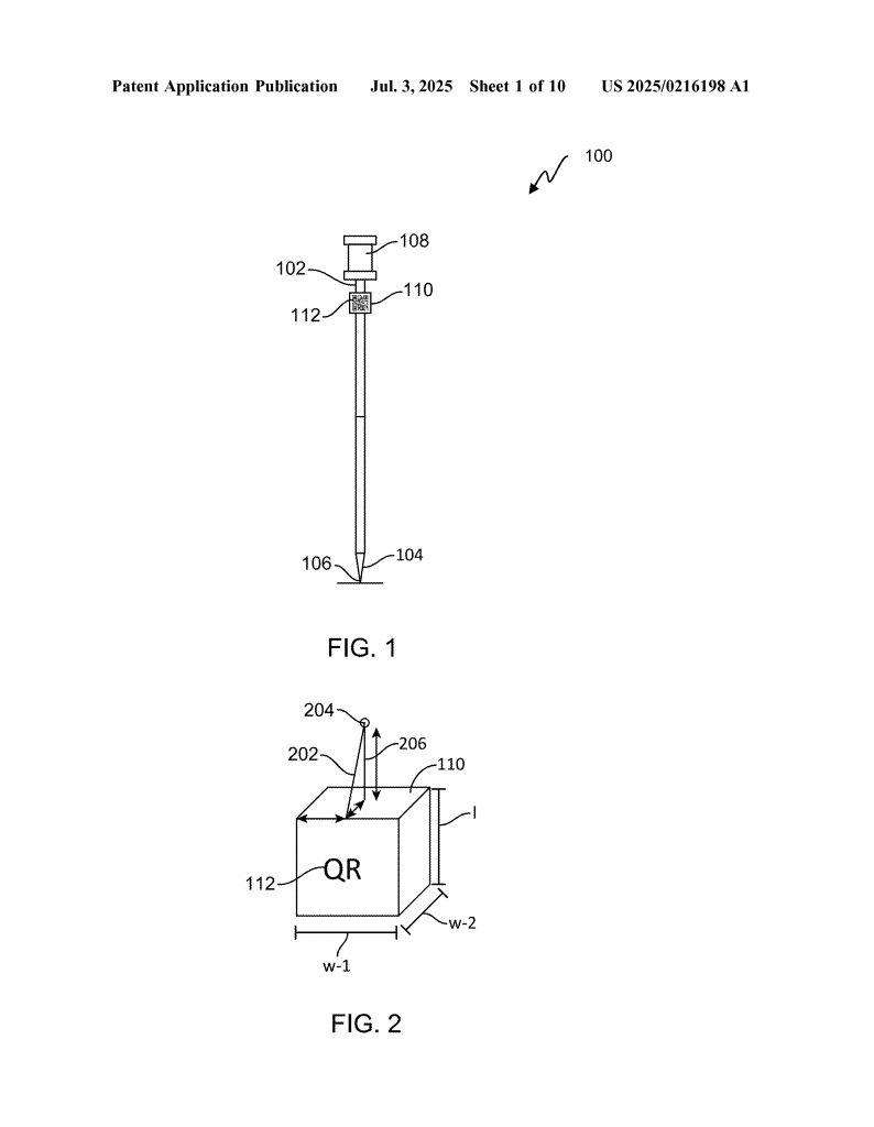
Imagine you are on a building site. You have a surveying pole with a reflector at the top and a special visual marker (like a QR code) nearby. The pole also may have a bubble level or even a camera. The total station is set up at a known position. Here’s what happens:
1. The total station shoots a laser at the reflector and measures its position very precisely.
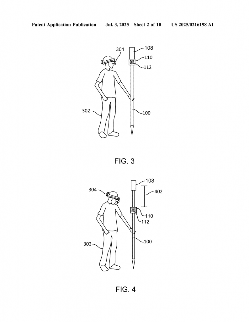
2. At the same time, a camera (either on an augmented reality headset, the pole, or the total station itself) takes a picture of the visual marker on the pole.
3. The camera’s software figures out the orientation (how much the pole is tilted and in what direction) by looking at the marker, which has a known size and position relative to the reflector.
4. The system knows the exact distance and angle between the reflector and the tip of the pole.
5. Using simple math, the system calculates where the tip is—even if the pole is not straight.
6. The result: you get the true location of the tip, which could be touching the ground, a wall, or a ceiling, without needing to keep the pole perfectly upright.
Key Innovations
This system is special because it combines two types of measurements: laser (from the total station) and vision (from the camera). Each has its strengths. The laser is very good at measuring distance to the reflector, but can’t see tilt. The camera, using the visual marker, is very good at figuring out tilt and angle, but not as precise at distance. By combining both, you get the best of both worlds.
Another smart part of this invention is how it uses the known relation between the parts of the pole. Since the marker and reflector are fixed at known spots, and their sizes and offsets are measured ahead of time, the system can easily turn a measurement of “where is the reflector?” and “how is the pole tilted?” into “where is the tip?” Not only does this work for poles, but also for robots, vehicles, or any rover with known geometry.
The system can work in several ways:
– The visual marker can be near the reflector for maximum accuracy, or lower down the pole for easier viewing.
– The marker can be a QR code, April Tag, or even just a colored shape, as long as the camera can recognize it.
– The camera can be on the headset, on the pole, or even on the total station.
– To measure orientation, the system can use one or more visual markers, inertial sensors, or a combination. For example, two markers allow for 6 degrees of freedom (position and orientation in 3D space).
It also supports both “outside-in” and “inside-out” modes. In outside-in, the total station looks at the rover. In inside-out, the rover looks at the total station or at markers in the environment. This flexibility means the system can be used in many different setups—handheld poles, robots, vehicles, or even drones.
Why This Matters
The main benefit is speed and ease of use. You no longer have to carefully level the pole every time you take a measurement. You can reach hard-to-get points (like corners or ceilings) quickly and accurately. Less training is needed, and there’s less chance for mistakes. On busy job sites or in places where only a few workers are available, this is a big help.
Accuracy is also improved. By always knowing the exact orientation, the system corrects for errors due to tilting. This is especially important in construction, where even small errors can cause big problems later. The system also supports ongoing correction—if the digital map in the headset drifts, simply looking at the marker snaps things back into place.
Another smart feature is the use of memory devices with special instructions. These are like tiny computers that remember how the parts relate, how to do the math, and how to show the results on a display, like in an AR headset. This makes the whole process smooth and automatic.
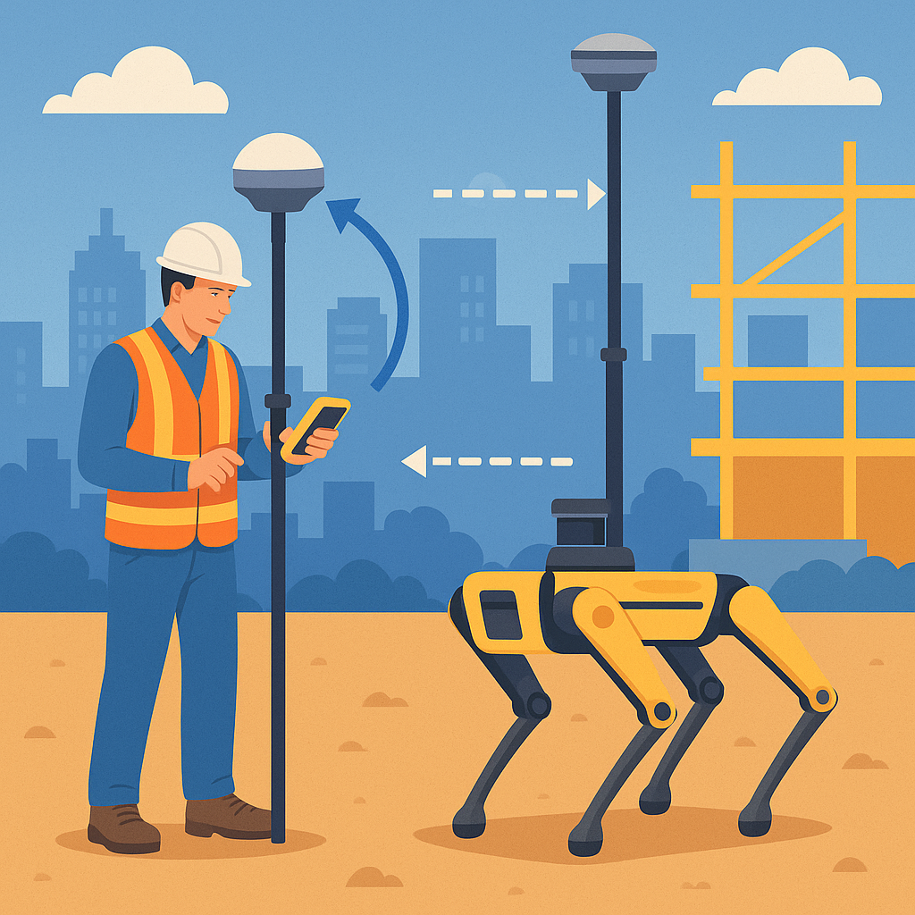
The system is also flexible. It can work with different types of rovers—simple poles, robots like Boston Dynamics’ Spot, vehicles, or even autonomous guided vehicles. The surveying device can be a total station, a GNSS receiver, or even a laser scanner.
The invention is ready for today’s tech world. It works with augmented reality headsets, smartphones, tablets, or any device with a camera. It can store models of the environment, overlay digital information, and help guide workers in real time.
Actionable Takeaways
If you’re a surveyor, construction worker, or engineer, this system means you can:
– Measure points faster, with less setup.
– Reach tricky spots without worrying about holding the pole straight.
– Work with less training and make fewer mistakes.
– Use AR headsets or tablets to see digital maps that always line up with the real world.
– Switch between different types of rovers or surveying devices as needed.
– Get more value from your equipment and finish jobs sooner and with higher quality.
Conclusion
Tilt-compensation surveying changes the game for anyone who needs to measure locations accurately. By combining the best of lasers and cameras, and by using smart software that knows how the parts fit together, this system lets you work faster, reach more places, and get better results. It’s simple, flexible, and powerful, and it opens up new possibilities for construction, surveying, civil engineering, and beyond. Whether you’re a seasoned professional or just starting out, this invention makes surveying easier, more reliable, and ready for the challenges of today’s job sites.
Click here https://ppubs.uspto.gov/pubwebapp/ and search 20250216198.