Invented by Scott Summit, Ethereal Matter Inc
One of the primary drivers of the market for VR haptic systems is the gaming industry. Gamers are always on the lookout for new and exciting ways to enhance their gaming experience, and haptic systems provide just that. With haptics, gamers can feel the impact of a punch, the recoil of a gun, or the texture of objects within the game. This level of immersion takes gaming to a whole new level, making it more realistic and captivating.
Beyond gaming, VR haptic systems have immense potential in other industries as well. In the healthcare sector, haptics can be used for medical training simulations, allowing medical professionals to practice procedures in a realistic virtual environment. This can significantly improve their skills and reduce the risk of errors in real-life scenarios. Additionally, haptics can be utilized in physical therapy, providing patients with a more engaging and interactive rehabilitation experience.
The automotive industry is another sector that can benefit greatly from VR haptic systems. Car manufacturers can use haptics to simulate the feel of driving different vehicles, allowing customers to experience the handling and performance of a car before making a purchase. This can revolutionize the car-buying process, as customers can make more informed decisions based on their virtual test drives.
Education is yet another field that can leverage the power of haptics in VR. Students can explore historical sites, conduct virtual science experiments, or even dissect virtual organisms, all while feeling the textures and sensations associated with these activities. This hands-on approach to learning can greatly enhance student engagement and understanding.
The market for VR haptic systems is expected to witness significant growth in the coming years. According to a report by MarketsandMarkets, the global haptic technology market is projected to reach $19.55 billion by 2026, with VR haptic systems playing a crucial role in this growth. Advancements in haptic technology, such as the development of more compact and affordable haptic devices, are driving the market expansion.
However, there are still challenges to overcome in the widespread adoption of VR haptic systems. The cost of haptic devices and the need for powerful computing systems to run VR applications can be barriers for some consumers. Additionally, the technology is still in its early stages, and further research and development are needed to improve the accuracy and realism of haptic feedback.
In conclusion, the market for VR haptic systems is poised for significant growth and innovation. From gaming to healthcare, automotive to education, haptics have the potential to transform various industries and provide users with immersive and realistic experiences. As technology continues to advance and costs decrease, we can expect to see more widespread adoption of VR haptic systems, revolutionizing the way we interact with virtual environments.

The Ethereal Matter Inc invention works as follows
A virtual-reality (VR) system consists of a VR display, a VR movement device that supports the user’s hands and feet with hand and foot interfaces. The VR movement apparatus allows the user to move their limbs in 3D space, including vertical, lateral and forward-backward movements. “A computer running VR software coordinates and synchronizes both the VR movement apparatus, and the VR display in order to provide users with simulated experiences within a VR environment.

Background for Virtual Reality haptic system
Virtual reality systems (VR systems) are computer-based programs that allow a user to experience a virtual three-dimensional world. Virtual reality systems are usually based on a visual head-set that allows users to virtually view and move in a computer-generated environment. Some VR systems enhance the visual experience with mechanical devices attached to the user’s skin to provide tactile force or resistance. These VR suits can be complex mechanical devices, which must be worn. Some VR suits offer a limited haptic sensation that is not appealing due to the overall experience. Other systems simulate flight and can make the user feel nauseated because bird-like flight is unfamiliar to humans. It is necessary to develop a new system that provides physical feedback and resistance to the system user without requiring them to wear mechanical devices.
A VR system may include a VR motion apparatus with hand and foot interfaces to support the hands and legs of a user. The VR movement apparatus allows the user to move their limbs in 3D space, not just along a horizontal or vertical motion plane. The VR movement apparatus allows users to simulate real physical activities like climbing in the same way they would do it in a real climbing environment.
The VR system could include a program running on a computer which synchronizes a user’s motion in a virtual environment through a display, and the VR movement apparatus to create a haptic effect. The display could be integrated into a VR head-set, which may also include an audio system. The visual signals can be coordinated with the VR movement apparatus control signals so that the virtual visual environment matches the limitations of the VR movement device’s hand and foot interfaces. The VR program can show a topographical VR world that includes virtual objects like land, mountains and structures. The VR software allows the hands and feet to move freely in the free space but prevents them from moving through virtual objects. This means that when the user makes virtual contact with any virtual structures, their movement stops. The VR visual display can be synced with these physical objects so that the user can feel and see the virtual objects.
In different embodiments, VR systems can be used to simulating various physical activities, such as walking, running or climbing. They can also simulate driving, cycling, swimming and rowing. VR machines can be used for physical therapy, training simulations and physical exercise. The VR system is a great way to safely train for dangerous activities like: skydiving or extreme skiing. The VR system is ideal for gyms, hotels, health clubs and other places where there are gyms or experience devices.
The present invention is a VR system which simulates physical and visual interaction with a three-dimensional digital VR environment. The VR system that is being invented can be a combination of a VR headset and a VR mechanical device to support the user. The VR headset allows a user to see a computer-generated VR three-dimensional (3D) world. This visual VR environment is then used to create a “haptic robot”. The movement apparatus coordinates the physical force expected in the VR environment with the force the user feels. This creates an illusion that is deceptive to both the visual and physical interactions, such as those felt by the hands and feet, and by extension, the arms, backs, legs, core muscle, etc. The inventive VR system creates a greater sense of immersion by adding bodily forces. The user “sees” The user?sees? The user will ‘feel’ the VR environment as they interact with it. “A simulated physical response would be felt by the user as they interact within the VR environment.
For instance, in one embodiment, a user could choose to virtually climb an object such as the Eiffel tower. Visually, the headset would allow them to “see”? The headset would allow them to?see? The user will see their digitally-created hands move within their field, such as reaching out to grab a spar or pulling down while ascending. The user would have physical contact with the haptic VR apparatus. The user’s hands, feet, and virtual environment would physically move in relation to each other, and to the virtual world, with the physical resistance seen through the VR headset. It was as if the user were climbing up. In one embodiment, the machine provides no resistance to upward motion. Gravity can re-center a user while ascending so that they are moving in the same place. The VR environment can have an incline in a running application. The user of the system can run in the VR environment by moving the legs. The VR movement apparatus will then re-center him using gravitational force so that he is running in place. If the user was in a VR mountain climbing environment, the VR motion apparatus could re-center him using gravitational force so that he is actually climbing in place.
In other embodiments, the user can use the VR system in order to experience other types of virtual activities, such as for entertainment, fitness or training. VR simulations can be used for a variety of purposes, including: burning calories, targeting specific muscle groups, rehabilitation, muscle memory development, etc. A digital controller can control the entire process. Each motion can be recorded and analyzed to determine the effectiveness of the routine. The doctor can then use this information to monitor a patient’s compliance with physical activity or progress in physical therapy. The VR system, in other embodiments can be used to monitor client training for a personal trainer or coach.
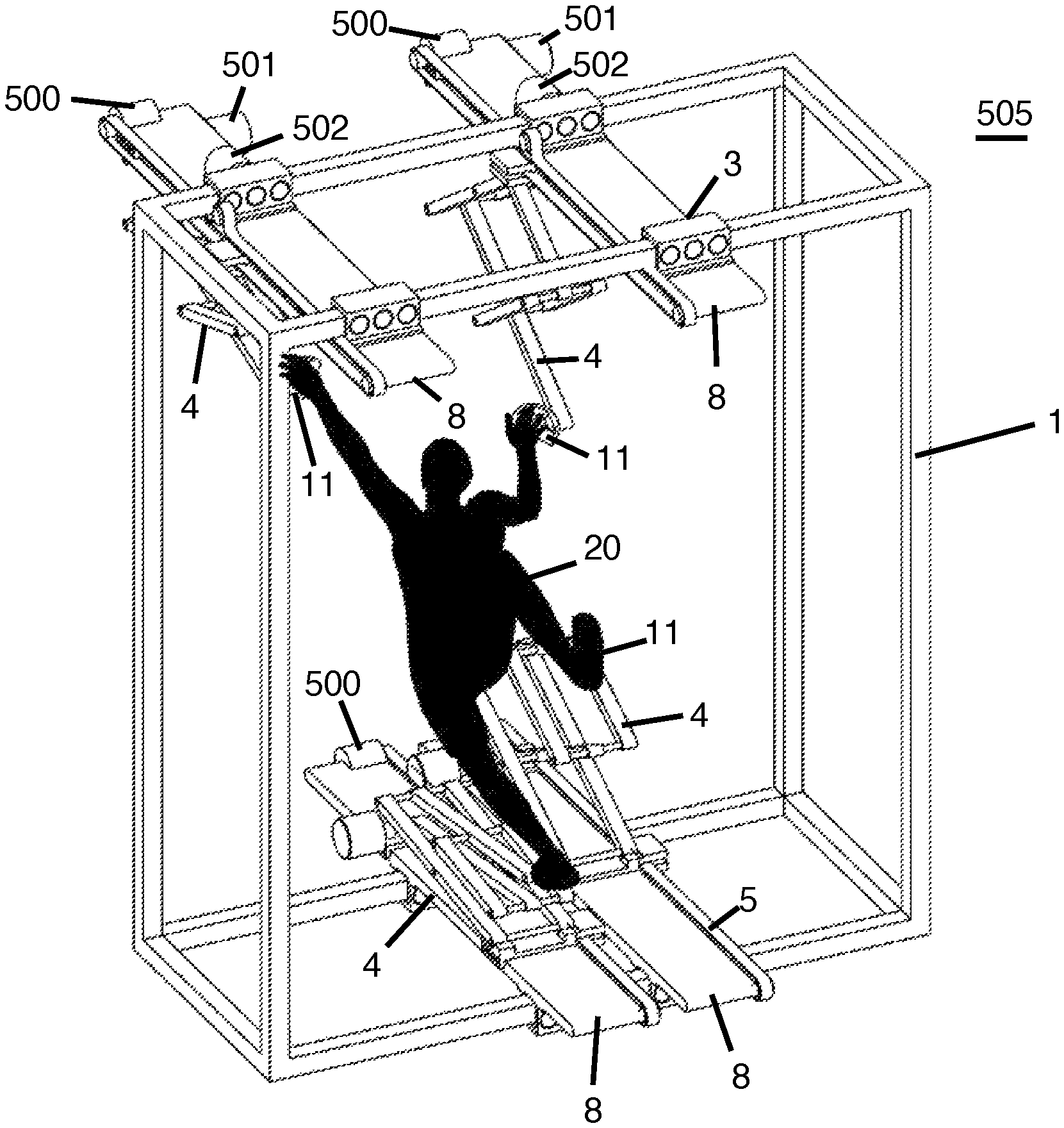
Referring to FIG. 1. A VR exercise apparatus 100 can be illustrated with a rigid frame 1, which can support all the members of the assembly. In one embodiment, the frame can include four identical armature assembly 2 mounted on linear bearings 3. The frame can then slide along the bearings. Movement of the armature assembly 2 can be described using an XYZ coordinates system. The linear bearings can allow the armature assembly 2 to slide laterally in the X-direction on the frame 1, with minimal friction. The linear bearings 3 can be coupled with carriages 8 to allow the scissor-jack mechanisms 4 to move in the Y direction relative to frame 1. Carriages 8 allow scissor-jack mechanisms 4 move in a Y direction with respect to frame 1. Each scissor-jack mechanism 4 can have a proximal end that is attached to the carriages 8, and a distal end which can be equipped with user interface mechanisms. The scissor-jack mechanisms 4 can expand and contract relative to frame 1 in the Y-direction. The distal ends of the four scissor-jack mechanisms 4 can be interacted with by the user. The scissor jack mechanism 4 can be coupled with: a left-hand interface, a rht-hand interface, a foot interface (left or right), and a foot interface (left or right) which can move in any X, Y or Z position defined by the frame. In one embodiment, the frame can define a X-Y “movement perimeter” The left hand interface and right hand interface as well as the left foot and right foot interfaces can all move within the XY movement perimeter. In the example illustrated, in the Z plane, there may be a user 20, the left hand, right hand, left foot, and right foot interfaces, as well as the left foot, right foot, and right foot interfaces.
Referring to FIG. A rigid frame is shown in a second embodiment. The frame 1 is a structure that supports the haptic device. It can be constructed from a number of straight tubes with a uniform cross-section, such as square, rectangular, round, or other suitable cross-sections. Tubes can be used as tracks for linear bearings. In another embodiment, frame 1 can be used to mount linear bearing tracks and slides on. In the embodiments illustrated, frame 1 can be a 3D-box with parallel tubes that extend in the XYZ directions. This defines a movement area within the apparatus. The linear bearings may slide along the outer surfaces. The tubes can have slots, and the linear bearings can slide over the inner surfaces of tubes.
Referring to FIG. A carriage 8 on the upper left is attached to linear bearings 3. This allows the carriage 8 to move smoothly along the upper tracks of the frame 1. For clarity, only one carriage 8 is shown. The linear bearings allow the carriage 8 move in the X-direction.

Referring to FIG. The upper left carriage 8 is shown with the frame 1, and an embodiment of the scissor-jack mechanism 4. The scissor-jack mechanism is coupled to carriage 8 by additional linear bearings which allow it to move in the Z directions relative to frame 1. The scissor-jack mechanism 4 is able to extend and contract in order to adjust the vertical positioning of a distal part. The distal ends can be connected to a foot or hand. The clamp and linear bearing assembly 5, which controls forward-backward motion, can be combined with a computer-controlled brake to regulate the gravity-driven descent by an end effector. The computer monitors the component movement to ensure that all end effectors move at the same speed during re-centering. If’vertical movement only’ is selected, the computer will monitor and control all component movements. When?vertical motion only? The scissor-jack mechanism 4 controls the vertical Y movement of the user as well as the location. “The linear bearings 3, carriage 8, and scissor-jack mechanism 4 are all part of the haptic device that links the three-dimensional movements of the user.
In order to simulate a 3D haptic VR environment, the haptic device can also be configured to resist or prevent movement of the distal end of the scissor-jack mechanisms 2. In the embodiment shown, the movement is controlled by a number of timing belts 6, shafts 7, and gears 17, which can control all the moving components of the haptic device. Timing belts 6 may include teeth that engage gear teeth. Gravitational pull by the user on the distal end of the linked scissor-jack mechanism 2 may cause the downward movement. The microprocessor can regulate this downward movement by using electric motors or brakes. The timing belts 5, spline wheels 17, and shafts 7 are used to link the lateral and forward-backward motions of foot and hand couplings on the distal end of the scissor mechanism 2. The motion vectors of the four end effects are then synchronized and identical. The four end effectors in an embodiment can be a left-hand interface, a corresponding right-hand interface, and a left-foot interface or a corresponding right foot interface.
Referring to FIG. A foreward-aft motor 19 or a lateral motor 18 can control the motions of the scissor-jack mechanisms 4. When engaged, the lateral control motor can drive the first timing belt 6, which connects the four carriages of the haptic device in a single, synchronized movement in the same directions. The fore-aft motor 19 can be attached to a gear 17 that drives a shaft 7. This shaft 7 can then rotate and move all four scissor mechanisms 2 in the Z direction simultaneously. The reverse rotation of the fore-aft motor 19 can move all four scissor mechanisms 2 backwards simultaneously. “The splined shaft 7, the splined shaft 17 at the top and bottom of frame 1, and a shaft 29 at base of frame 1, are all connected by a timing belt 28 to force simultaneous motion of upper and lower scissor-jack mechanisms 2.
FIG. The haptic device is shown in a perspective close-up view on FIG. In this embodiment, the motor fore-aft 19 can be coupled directly to the splined sleeve 7, which extends along the width of frame 1. The gear 17 is mounted at the opposite end to the splined sleeve 7 and a belt 28, which surrounds the gear 17, extends downward on the right-hand side of frame 1, controls the rotation of a second splined sleeve 29 that extends along the bottom edge of frame 1. Around the splined sleeve 7, a sliding shaft gear 12 is mounted that can rotate and slide with the shaft 7. The carriage 8 is fitted with the sliding shaft gear 12. It controls the movement in Z of the scissor-jack mechanism 4 relative to the carriage. The splined sleeve 17 can rotate a drive that controls the carriage’s fore and aft motion. It can also include a chain which controls the scissor-jack mechanism 2’s fore-aft movements relative to the carriages 8.
The lateral control motor is coupled with a gear that controls the movements the belt 6. This belt extends from the top width of frame 1, bends down and extends along the right side and bottom horizontal surface. The carriages can be connected to the belt 6, so that the carriages can move in either direction.
FIG. The figure 7 shows a left-side orthogonal perspective of a particular embodiment of the invention VR movement apparatus. The hands of the user 20 grip end effectors 11. End effectors 11 may be left hand interfaces and right hand interfaces that can be grabbed by either the left or right hand of the user. At the distal end of the leg scissor-jack mechanisms, the user’s feet may be attached to the left foot and right foot interfaces with straps or bindings that are similar to bicycles. The scissor-jack mechanisms move forward and backward in the Z direction using linear bearings 10.
The bearings 10, the carriages, and the scissor-jack mechanisms are free to move when they’re in a state of?free movement? state. When the user virtually “grips” When the user virtually ‘grips’ When controlled by the computer, the scissor-jack mechanisms 4 and carriages 2 are immediately clamped to their specific timing belts 6, allowing them to simulate contact with VR objects. Some or all scissor-jack mechanisms 4 may be able to hold the user in a fixed place at a VR object contact point. The scissor-jack mechanisms may move together to center the user within the movement boundary of the frame 1 if the VR software on the computer indicates re-centering. The computer can center the end effects 11 by moving them in the same positions relative to each other.
Each carriage can have a sliding shaft 12 that is coupled with the timing belts mounted on the carriage. This sliding shaft gear is keyed into a spline (not shown here), which allows all belts move at the same time. Pulleys 13 mounted at the opposite ends are free-spinning, forming a tight loop with the timing belt 6. The scissor-jack mechanisms 4 move in the Z-direction when the timing belt 6 moves.
FIG. “FIG. 8 shows a rear orthogonal view in elevation of a VR embodiment. The belt-clamps are in the’released’ position. The four armature assembly 2 can move freely in a side-to-side motion while the linear bearings slide along the frame 1 to minimize friction. In a similar way, the forward-aft (Z direction), and upward-downward motions (Y direction) are free for user 20 to move in’released’ state. The end effectors 11, located on the hands 10 or feet 9, are where the user 20 makes contact with the invention. The timing belts and the splined shafts are used to link all downward forces, so the total downward pressure can always equal the weight of the user. The scissor-jack mechanisms can be in a fixed state when the belt clamps are engaged. This simulates a solid structure for the user’s feet and hands. The visual confirmation that the structure is not moving, generated by a computer, can be seen on the VR headsets or other visual displays.
The scissor-jack mechanism 4 is able to move in all directions, vertical, horizontal, forward-backward, as required, and in synchronized motion to bring the user to the center of frame 1. This prevents the scissor-jack mechanisms from moving outside or into contact with the movement perimeter.

Referring to FIG. In Figure 9, several motion vectors in the X, Y and Z directions are shown. To create controlled and deliberate re-centering, the user must ‘climb’. The scissor-jack mechanisms are synchronized to move forward and backward, laterally, and in an elongated or contracted manner. The overall vector 35 is determined by a combination of the downward motion 32, the fore-aft movement 33 and the lateral motions 34. This occurs as the end-effector is re-centered between the starting position 30 and the final position 36. Microprocessors control the motors and the brakes to move the end-effector along the vector 35.

Click here to view the patent on Google Patents.