Invented by Majd Bakar, David Deephanphongs, Google LLC
In today’s digital age, images play a crucial role in various industries, including advertising, marketing, e-commerce, and entertainment. Whether it’s a product photograph, a social media post, or a movie poster, businesses and individuals strive to create visually captivating images that grab the viewer’s attention. This has led to the emergence of a thriving market for systems, methods, and media that enable users to adjust and enhance images to meet their specific requirements.
One of the key drivers behind the growth of this market is the increasing accessibility of image editing tools and software. In the past, image editing was limited to professionals who had access to expensive and complex software. However, with the advent of user-friendly applications and online platforms, even individuals with limited technical expertise can now edit and adjust images effortlessly. This has opened up new opportunities for businesses and individuals to create visually stunning content without the need for extensive training or expensive equipment.
Furthermore, the rise of social media platforms and the need for engaging visual content have fueled the demand for image adjustment tools. Users are constantly seeking ways to enhance their photos, apply filters, and make their images stand out from the crowd. As a result, developers and software companies have been quick to cater to this demand by providing a wide range of systems, methods, and media that enable users to adjust and manipulate their images with ease.
The market for systems, methods, and media for adjusting images is not limited to just software applications. It also includes hardware devices such as cameras, scanners, and printers that enable users to capture, digitize, and reproduce images with high precision. These devices often come equipped with built-in features and settings that allow users to adjust various aspects of the image, such as brightness, contrast, and color balance.
In addition to the consumer market, the demand for image adjustment systems and methods is also prevalent in industries such as healthcare, forensics, and scientific research. In medical imaging, for example, professionals rely on advanced systems and methods to adjust and enhance images for accurate diagnosis and treatment planning. Similarly, forensic experts use image adjustment techniques to enhance and analyze images for criminal investigations.
As the market for systems, methods, and media for adjusting images continues to grow, so does the competition among software developers and hardware manufacturers. Companies are constantly innovating and introducing new features and functionalities to stay ahead in the market. This has led to the development of cutting-edge technologies such as artificial intelligence and machine learning, which can automatically adjust and enhance images based on predefined parameters or user preferences.
In conclusion, the market for systems, methods, and media for adjusting one or more images displayed to a viewer has experienced remarkable growth in recent years. The increasing demand for visually appealing content, coupled with the accessibility of image editing tools and the rise of social media, has fueled the need for systems and methods that enable users to adjust and enhance their images effortlessly. As technology continues to advance, we can expect further innovations in this market, leading to even more sophisticated and user-friendly image adjustment solutions.

The Google LLC invention works as follows
The invention provides systems, methods and media that adjust one or more displayed images to a viewer. In some implementations, the systems comprises at least one circuit capable of: detecting an orientation of a user based upon at least two points that are associated with the user; determining, based upon the orientation, a position for rotation of a first display image; and generating a display picture to display on the screen, which includes at least a part of the first display image rotated according to the rotational location.

Background for Systems, Methods, and Media for Adjusting One or More Images Displayed to a Viewer
The present disclosure is a general one that relates to displays. The present disclosure is more specific, and relates to the adjustment of a display according to an orientation of a user.
The video is displayed horizontally on televisions and other screens in a manner that best suits an upright (vertical head display). This display mode is the one that television viewers are used to. However, this is not ideal for viewers who tilt their heads (to the right or left, or even to the back), or when they are not in an upright position (e.g. laying on the side, or reclined). The image may not be optimal for viewing if the viewer is slouching in the chair or resting their head on the pillow when seated on a bed.
The disclosure includes systems, methods and media that adjust one or more displayed images to a viewer. According to some implementations, a system is provided for adjusting images displayed to viewers. The system comprises: At least one processing circuit that can detect the orientation of the viewer using at least two points. It can also determine a rotational location of a first picture to be displayed on an display based upon the orientation.
According to some implementations, a method is provided for adjusting images that are displayed to a user. The method includes: detecting an orientation of the viewer using a hardware processor based upon at least two points related to the viewer; determining a rotational location of a first picture to be displayed on display based upon the orientation; and creating a display for display on display which includes at least a part of the first photo rotated according to the rotational positioning.
According to some implementations, non-transitory computers-readable media contain computer executable instructions which, when executed by the processor, cause the process to perform a procedure for adjusting the video displayed to the viewer. The method comprises: detecting the orientation of a user based upon at least two points that are associated with the user; determining a rotational location of a video to be displayed on an display based on this orientation; and generating a displayed image for display on the screen, wherein the displayed image
Referring to the figures in general, systems and techniques for adjusting images for display to a viewer are described and shown. The disclosure is a system for determining the orientation of the viewer. For example, the head position of the viewer or the eye axis. The system aligns an image displayed on a display device (e.g. a TV or monitor) with the head and/or the eye axis based on the head and/or the eye axis. In one implementation, the image is adjusted without moving the television housing or monitor, although alternative implementations may also adjust the housing. The system adjusts the image to the head position or orientation rather than a horizontal orientation. In one implementation, it is possible to determine the position and/or the orientation of the eye of the viewer and adjust the display based on that information. Other data can be inferred based on the eye and/or head axis, which may help determine the state of mind or attitude of the viewer. Additional viewing parameters, such as image display settings like brightness and contrast, sound settings, auto off, etc., can then be adjusted. “The display may be adjusted to suit the viewer.
The disclosure also relates to the displaying of supplemental information on the display. This may be used, for example, as a supplement to a video, html page or other displayed content. The supplemental information may be displayed on the screen in the empty space left by the image, after it has been adjusted. As an example, when a 90-degree image is rotated, the aspect ratio may be preserved, leaving a blank portion of the screen next to the image. This area can be filled with additional data such as a guide to the program, controls for playing content (e.g. stop, pause and volume), etc. This portion can be filled with supplemental data, such as a program guide, controls for the content being played, (e.g. stop, pause, volume, etc.), or web content that is related to the content playing, (e.g. blogs, wikis and messaging, such as tweets). “Or any other supplemental material.
Referring to Figure 1, it is shown that the systems and methods of this disclosure can be applied in an environment 100. 1 shows an environment 100 where the systems and methods disclosed herein may be used. The environment 100 shown is an example of how a display configuration and viewer can be used in a room. However, the disclosure may also be applied in other settings.
Environment 100 includes a display device and a viewer watching the display. In the implementation shown in FIG., display 102 is part of a TV. 1. Display 102, according to other implementations may be an electronic display (e.g. television, laptop, PC, etc.). Or any other electronic source (e.g. video game consoles, etc.). Display 102 provides a display to viewer 104.
A television set-top box (108 shown with a viewer orientation detection device) 106″ The viewer orientation detection device 106 can be any device that is configured to determine an orientation (e.g. a head orientation or eye axis of the viewer) of display 102. In one implementation, viewer orientation detection device 106 comprises a camera. The systems and methods described in the present disclosure refer to viewer orientation detector device 106 as being a camera. However, other implementations may include any detection device that is configured to detect the position and orientation at least of a portion or viewer 104. It may also be any type sensor that detects a location or behavior of viewer or 104. According to one implementation, the device for detecting viewer orientation may be an infrared or laser detector that detects at least one of the position and orientation at least a part of a viewer. In another implementation, a viewer orientation device can be used with a device that is worn by the user (e.g. a laser emitting device) and which communicates with the device. Set-top box (108), which receives data from the viewer orientation detection device, determines the orientation of viewer 104. The viewer orientation detection device may also be coupled to display 102, a remote source or any other device configured for applying rotational position adjustment to an image to display on display 102, according to various implementations.

In the implementation of FIG. Since display 102 represents a television, set-top box (TV) 108 is displayed and configured to supply the television with the content it needs to display. Display 102 can be used as a display on another electronic device, such as a monitor, and set-top boxes 108 are not required in other implementations.
Viewer 104 can be seen watching the display 102 from a couch or seat 110. Viewer 104 could be tilting his head at an angle to display 102 as he watches display 102. It could be as a consequence of lying down on a sofa or chair, standing or sitting, or any other motion. Display 102 has traditionally been configured to display content for viewer 104 when the viewer is upright (e.g. eye axis is generally parallel to the horizontal dimension of monitor). Viewer 104 is not able to view the content of display 102 with his head at an angle.
Referring to FIGS. The viewer orientation detection device can be used to determine the position of the viewer’s head and eye axis in FIGS. The location of the viewer’s head may be determined when determining its position. The head location can be represented, for example, as coordinates within a three-dimensional space (e.g. (x,y,z) coordinates or polar coordinates. The head location may be expressed in two-dimensional (2D), or three-dimensional (3D) space. For example, the (x,y) coordinates may represent an absolute distance to the display. The orientation of the body may also be determined. This may involve determining whether the head is facing the monitor directly or not.
The eye axis can be determined when the position of the viewer is known. The eye axis can be defined by the line connecting the two locations of the eyes in 2D or 3-D space. The eye axis can be determined using any of a number of techniques, such as those that are used with facial recognition software or techniques. Light reflected by the eyes of the viewer 104 may be sensed and analyzed using a camera in the viewer orientation detection device. The eye detection methods can vary depending on the implementation.
In FIG. Viewer 200 could be observing display 102 from an upright horizontal position. It is possible to determine the eye location 204, and eye axis 200 of the viewer. In FIG. In FIG. 2A, the eye axis is shown as horizontal line. This indicates to monitor 102 that a viewer is in a horizontal upright position, and no display adjustment is required. Eye axis is a horizontal line that has the same coordinates in both directions. (For example, both eyes have the same y- and the same z-coordinates, which indicates they are at the exact same depth from the display, and the same relative height.) The x-coordinates are different, and represent the distance between the two eyes.
As another example, FIG. Viewer 250 is shown in 2B at an angle (e.g. angle A) which is offset relative to the horizontal axis of display 102 (e.g. x-axis). Viewer 250 can be lying down or tilting their head in any other way to view display 102. A processing circuit in the viewer orientation detection device or set-topbox 108 can determine the position of the head, as well as the orientation. In FIG. In FIG. The viewer could be looking at display 102, which is located to the left of the center.
The eye locations 253, and/or the eye axis of viewer 250 can be determined. The head of viewer is at a different angle from the horizontal axis in relation to display 102. Therefore, eye axis may be a straight line with different coordinates (on (x,y,z) axis). This indicates that the distance between each eye and display 102 varies. One eye 254 can be “higher” than the other. In a y axis dimension, one eye 254 may be?higher? than the other. This will change the perspective of viewer 250. The eye axis 252 can be used to determine the rotational position on display 102 of an image that corresponds with the eye axis. In FIG. 4-8. One or more coordinate values for each eye can be ignored; for example the fact that the eye axis is 252 at an angle of A with display 102 may not matter. The system can be configured to determine angle A, and then adjust the display orientation 102 in accordance with angle A.
In one implementation, parts of the viewer’s head may be used in determining the eye axis and/or head position. The location of a viewer’s forehead or chin can be determined. Based on this location, the eye axis and head position may be determined. The forehead or the chin can also be used to determine whether or not the viewer is leaning backwards or forwards. “For example, a forehead that is farther away from the screen than the chin will indicate a viewer leaning in the opposite direction.
Referring to FIGS. In FIGS. In FIG. In FIG. The image 302 on display 300 is not adjusted when a viewer (e.g. viewer 200) is viewing it in a vertical position. Image 352 can be rotated or tilted in other implementations. It may also be stretched or rotated. Image 352 can be rotated only if a viewer is on one side of the screen, stretched if a viewer’s face is not facing the display or tilted if he is above or beneath the display.
In FIG. “In FIG. The head position of the viewer (such as viewer 250) and its eye axis will cause images to be stretched. The image is adjusted so that the plane is compatible with eye axis.

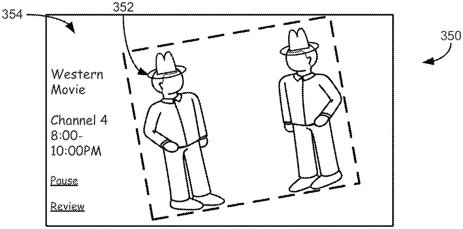
In FIG. The image 352 in 3B is shown with a boundary to delimit the area on display 350 where the image is displayed. The border can be seen by the viewer or not, depending on the implementation. The display space of display 350 is unused when image 352 rotates. In one implementation, the space left unused may be used to show supplemental data 354 The supplemental data 354 can include information about the program (e.g. air times, channel info, etc.) or the name of it. The controls of the display can be selected by the viewer via the television remote (e.g. the viewer can choose to pause or stop it).

Click here to view the patent on Google Patents.