Invented by Cezar Morun, Stephen Lake, Meta Platforms Technologies LLC
One of the key players in the market for CEMG sensors is the medical device industry. Companies such as Delsys, Noraxon, and Myonexus are leading the way in developing CEMG sensors and related products. These companies offer a range of products including sensors, amplifiers, software, and accessories that are designed to work together to provide accurate and reliable muscle activity measurements.
In addition to the medical device industry, there are also a number of academic and research institutions that are actively developing new systems, articles, and methods for CEMG sensors. These institutions are focused on advancing the technology and improving the accuracy and reliability of CEMG sensors. Some of the key areas of research include signal processing, electrode design, and data analysis.
The market for CEMG sensors is also being driven by the increasing demand for wearable technology. Wearable CEMG sensors are becoming more popular among athletes, fitness enthusiasts, and individuals who are looking to monitor their muscle activity during exercise or physical therapy. These sensors are typically smaller and more lightweight than traditional CEMG sensors, making them more comfortable to wear for extended periods of time.
As the market for CEMG sensors continues to grow, there is a need for standardized testing and validation protocols. This will ensure that the sensors are accurate and reliable across different applications and environments. The International Society of Electrophysiology and Kinesiology (ISEK) is one organization that is working to establish these standards.
In conclusion, the market for systems, articles, and methods for CEMG sensors is rapidly expanding. The medical device industry, academic and research institutions, and the growing demand for wearable technology are all driving this growth. As the market continues to evolve, there will be a need for standardized testing and validation protocols to ensure that CEMG sensors are accurate and reliable across different applications and environments.

The Meta Platforms Technologies LLC invention works as follows
Systems, articles and methods for improving capacitive electromyography? (?EMG?) sensors are described. One or more sensor electrodes are coated with protective barriers made of a material with a relative permittivity of 10 or higher. The protective barrier protects the sensor electrodes from moisture, sweat and skin oils. While allowing for a high capacitance between sensor electrode(s), and user’s body, it is also beneficial. The improved capacitive EMG sensor provides enhanced resistance to environmental and skin conditions. These improved capacitive EMG sensor are especially well-suited to wearable EMG devices, which may be worn for extended periods of time or under different skin and environmental conditions. This article describes a wearable EMG device which provides a component to a human-electronics interface. It also incorporates improved capacitive EMG sensor technology.

Background for Systems, articles and methods for capacitive electrodemyography sensors
Technical Field
The present systems and articles are generally related to electromyography, particularly capacitive electromyography sensor sensors.
Description of Related Art
Wearable Electronic Devices.
Electronic devices are now commonplace in most parts of the world. Electronic devices are now small enough to be easily carried thanks to advances in integrated circuit technology. These electronic devices are ‘portable’. These electronic devices can include on-board power supplies (such batteries or other power storage system) and may operate without wire-connections to any other electronic systems. However, small and lightweight electronic devices can still be considered portable, even if they have a wire-connection to another electronic device. A microphone, for example, can be considered portable regardless of whether it is connected wirelessly or wired.
The portability of electronic devices has created a large industry. There are many types of portable electronic devices, including smartphones, ebook readers, laptop computers and tablet computers. The convenience of carrying a portable electronic device around has brought with it the inconvenience of having your hand(s) encumbered. An electronic device can now be worn, and is portable.
A wearable electronic device can be any electronic device that the user can hold onto without having to physically grasp, grip, or clutch it. A strap, band, or band may attach a wearable device to the user. An adhesive clip, pin and clasp, article of clothing, tension, elastic support, interference fit, or other form can also be used. Wearable electronic devices can include electronic wristwatches and electronic armbands, electronic rings or electronic ankle-bracelets. Head-mounted electronic display units, hearing aids and so forth.
Human-Electronics Interfaces
A wearable electronic device can provide direct functionality to a user (such audio playback, data display and computing functions). It may also provide electronics that allow the user to control, interact with, or receive information from another electronic device. A wearable electronic device might include sensors that can detect inputs and send signals to other electronic devices based on them. There are many types of input-types and sensor-types. These include tactile sensors (e.g. buttons, switches or keys) that provide manual control, acoustic and electromyography sensors that provide gesture control and/or accelerometers that provide gesture control.
A human-computer interaction (?HCI?) An example of a human/electronics interface is the “Human-computer interface (?HCI)”. These systems, articles and methods can be applied to HCIs but could also be used to any other human-electronics interface.

Electromyography Sensors
Electromyography (?EMG?) “Electromyography (?EMG?) is the process of detecting and processing electrical signals that are generated by muscle activity. EMG devices use EMG sensors that respond to the ranges of electrical potentials involved in muscle activity (typically?V?mV). EMG signals can be used for a variety of purposes, such as medical monitoring, diagnosis, exercise and training, rehabilitation, and controlling electronic devices’ functions.
There are two types of EMG sensor: intramuscular EMG and surface EMG. The intramuscular EMG sensor is designed to penetrate the skin to measure EMG signals within the muscle tissue. Surface EMG sensors, on the other hand, are intended to be placed on the skin’s surface and measure EMG signal from there. The intramuscular EMG sensor measurement can be more precise than the surface EMG sensor measurements, but they must be applied by a trained professional. They are also more invasive and less desirable for patients. In general, intramuscular EMG sensor use is restricted to clinical settings.
Surface EMG sensors are easier to use, more comfortable for patients/users, and therefore are more suitable for non-clinical settings. EMG is used in human-electronics interfaces, such as those described in U.S. Pat. Nos. Nos. There are two types of surface EMG sensors: capacitive EMG sensor and resistive EMG sensor. The sensor electrode for both types of surface EMG sensors typically contains a plate of electrically conducting material that is placed against the skin or very close to it. An EMG sensor electrode that is resistive is usually directly connected to the skin of the user, while one that is capacitively coupled is more likely to be electrically coupled. The sensor’s performance can be affected by skin conditions and environmental factors such as humidity, hair density, moisture, and so forth. For resistive EMG sensors, these parameters can be controlled by prepping the skin of the user before applying the electrodes. To create a stable and suitable environment, the area of skin to which a resistive electrode will be applied is typically shaved and exfoliated. This limits the appeal of resistive EMG sensor to home and/or leisure users. Capacitive EMG sensors have the advantage of being more resistant to certain skin and environmental conditions. They are often applied without the need for elaborate skin preparation (e.g. shaving, exfoliating and applying conductive gel). Capacitive EMG sensors can still be sensitive to moisture. They may suffer from poor performance if the user sweats. Capacitive EMG sensors that are more robust against environmental and skin conditions is needed.
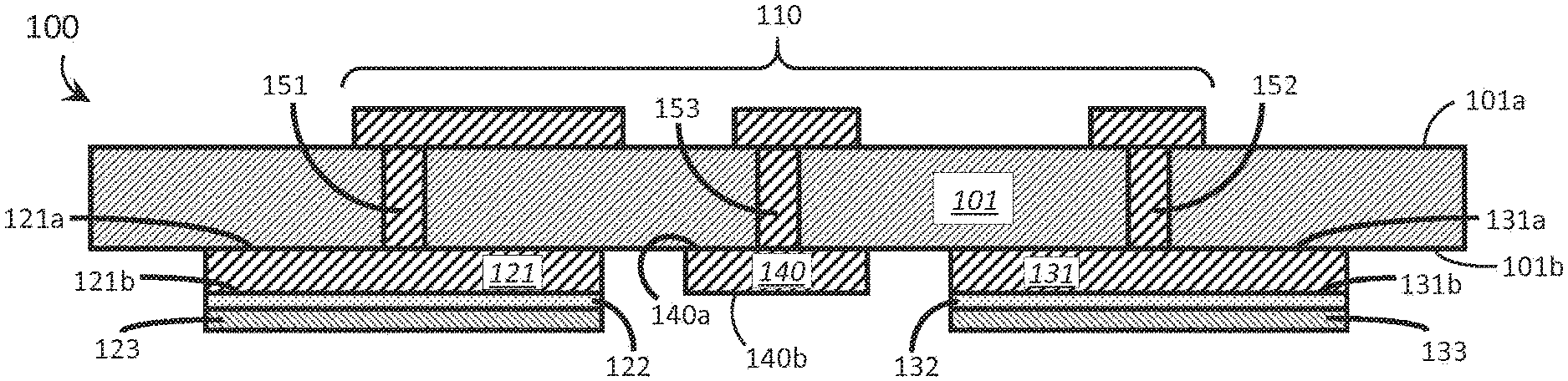
A capacitive electromyography (?EMG?) “Capacitive electromyography (?EMG?) sensor” A material containing copper may be used as the first sensor electrode. Circuitry can include at least one circuit from the following group: an amplifier circuit, a filtering and an analog-to digital conversion circuit. The substrate may carry at least some of the circuitry. A substrate may have a first and second surface. The second surface may be located across the thickness of the substrate. At least some of the circuitry and the first electrode can be carried by either the first or second substrate surface. A ceramic material may be used as the dielectric layer. An X7R ceramic material may be used as the dielectric layer. A laminate structure may be formed by the substrate, first sensor electrode and dielectric layer. An electrically conductive epoxy may be sandwiched between the dielectric and first sensor electrodes of the capacitive EMG sensor. The electrically conductive epoxy binds the dielectric layer to the first sensor by adhering it to the electrode. Alternately, the capacitive EMG sensors may also include an electrically conductive solder sandwiched between the dielectric and first sensor electrodes. The electrically conductive solder attaches the dielectric layer to the first sensor by electrically connecting the solder. The thickness of the dielectric layer can be less than 10 micrometers. A capacitive EMG sensors may also include a second electrode. The second electrode comprises an electrically conducting plate with a first surface facing the substrate and a second, opposite surface, across the thickness of the second electrode. The second electrode is communicatively coupled with the circuitry and the dielectric layer covers the second electrode’s surface. A single continuous layer of dielectric material may be used to cover both the second electrode’s second surface and the second electrode’s second surface. A first section may cover the second electrode’s second surface. At least one second section covers the second electrode’s second surface. The first section of dielectric material is physically distinct from the second section. The first and second sensors electrodes may be nearly coplanar. The capacitive EMG sensor could also include a ground electrode. This ground electrode may be carried by the substrate. It comprises an electrically conducting plate with a first surface facing the substrate and a second, opposite surface across the thickness of ground electrode. The ground electrode is communicatively coupled with the circuitry and the second surface is exposed. A capacitive EMG sensor could also include an additional layer sandwiched between the substrate and the first sensor electrode.
A method for fabricating a capacitive EMG sensors may include: forming at most a portion on a substrate’s first surface; forming a second sensor electrode on the substrate’s second surface, the second substrate surface opposite the substrate’s first surface; creating at least one electrically conducting pathway that communicatively links the first electrode and at least one portion of the circuit; and covering the first electrode with a dielectric coating consisting of a dielectric material with a relative permittivity at minimum 10. The first sensor electrode may be coated with a dielectric coating. A ceramic material may be used to coat the first sensor layer with a dielectric coating. The first sensor electrode may be coated with an X7R ceramic substance. The capacitive EMG sensors may be differential capacitive EMG sensors. Further steps may include: forming a second electrode on the second substrate surface, wherein the second electrode comprises an electrically conducting plate; creating at least one electrically conductive pathway that communicatively couples at least one circuit to the second electrode; and then coating the second electrode with the dielectric material. A ground electrode may be formed on the second substrate surface. The ground electrode is an electrically conducting plate. At least one electrically conductive pathway is created that communicatively links the ground electrode with at least a portion or all of the circuits. The first sensor electrode may be coated with a dielectric coating. However, the dielectric coating should not be applied to the ground electrode. The first sensor electrode may be coated with a dielectric coating. This may also include covering the ground electrode as well as the first sensor electrode. The first sensor electrode may be coated with a dielectric coating. This could include putting a layer electrically conductive epoxy on it; then putting the dielectric layer on that layer. The first sensor electrode may be coated with a dielectric coating. This could include a layer electrically conductive solder being placed on the electrode. Finally, the dielectric layer can be deposited on top of the layer of electrically conductive solder.
A wearable EMG system may include at most one capacitive EMG sensors that are responsive to (i.e. to detect and provide one(s) or more signals in response to) muscle activity. The first electrode is composed of an electrically conductive electrode. A processor is communicatively coupled with the at minimum one capacitive EMG sens to process the signals from the sensor. An output terminal is communicatively connected to the processor to transmit the signals. A ceramic material may be used as the dielectric layer. A ceramic material could include an X7R material. Circuitry may be included in the wearable EMG device to mediate communicative coupling of the at least 1 capacitive EMG sensor with the processor. The circuitry could include at least one circuit from the following group: an amplifier circuit, a filtering and an analog-to digital conversion circuit. The thickness of the dielectric layer in at least one capacitive EMG sensors may not exceed 10 micrometers. At least one capacitive EMG sensors may contain a differential capacitive EMG sensing device. The differential capacitive EMG sensors may also include a second electrode with an electrically conductive plat. In this case, the dielectric layer covers the second electrode. A ground electrode may be included in the at least one capacitive EMG sensors. This ground electrode comprises an electrically conductive plat and is exposed to the elements without being covered by the dielectric.
BRIEF DESCRIPTION ABOUT THE VIEWS FROM THE DRAWINGS
Identical reference numbers are used to identify elements or acts that are similar in the drawings. Drawings may not be drawn to scale due to the relative sizes and positions of elements. The shapes and angles of elements and angles are not drawn at scale. Some elements have been arbitrarily enlarged to make it easier to read. The particular shapes of elements drawn do not convey information about the exact shape of the elements and were chosen for easy recognition in the drawings.
FIG. “FIG.

FIG. “FIG.
Click here to view the patent on Google Patents.