Invented by Anatoliy Parpara, Ivan Kharpalev, Stephan Albert Alexandre Dumothier, Andrey Cherkas, Alexey Kalinichenko, Jack Shaw, Israel Velazquez, Align Technology Inc
Orthodontic aligners are a type of dental appliance that are used to straighten teeth and correct bite problems. They are typically made of clear plastic and are worn over the teeth for a period of several months to a few years. Orthodontic aligners are becoming increasingly popular because they are more discreet than traditional braces, and they can be removed for eating and cleaning.
The market for orthodontic aligners is expected to grow at a compound annual growth rate of 18.3% from 2020 to 2027, according to a report by Allied Market Research. This growth is being driven by factors such as the increasing prevalence of malocclusion (misaligned teeth), the growing demand for cosmetic dentistry, and the development of new technologies that make it easier to provide orthodontic treatment.
One of the key players in the market for orthodontic aligners is Align Technology, the company behind the popular Invisalign system. Invisalign uses a series of clear plastic aligners to gradually move teeth into the desired position. The company has been growing rapidly in recent years, with revenue of $2.4 billion in 2019, up from $1.8 billion in 2018.
Another player in the market for orthodontic aligners is SmileDirectClub, a direct-to-consumer company that offers at-home aligner kits. Customers take their own impressions using a kit provided by the company, and then receive a series of aligners in the mail. SmileDirectClub has been growing rapidly, with revenue of $750 million in 2019, up from $423 million in 2018.
In addition to orthodontic aligners, there is also a growing market for other types of dental appliances, such as clear aligners for minor tooth movement, retainers, and night guards. These appliances are used to treat a variety of dental problems, such as teeth grinding, snoring, and sleep apnea.
Overall, the market for systems and methods for providing orthodontic aligners and other dental appliances is expected to continue growing in the coming years. This growth is being driven by factors such as the increasing demand for orthodontic treatment, the development of new technologies, and the growing popularity of direct-to-consumer models. As the market continues to evolve, we can expect to see new players enter the space and new innovations that make orthodontic treatment more accessible and affordable for patients.

The Align Technology Inc invention works as follows
A method of manufacturing an orthodontic aligner involves printing a mold that is associated with a patient’s dental arch, then forming the aligner on top of the mold and trimming it. Further, the method involves assessing the quality of an orthodontic alignmenter by receiving a digital representation. The digital representation was generated using imaging of the aligner. After analyzing the representation, it is possible to determine if the aligner contains a manufacturing defect.

Background for Systems and Methods for Providing Orthodontic Aligners and Other Dental Appliances
For some applications, shells can be formed around molds in order to create a negative mold. Shells are then removed and re-used for different purposes. A shell may be formed around a mold to be used later for corrective dentistry and orthodontic treatment. The mold could be a positive mold for a patient’s dental arch, and the shell might be an aligner for one or more of the patient’s teeth. The mold can also contain features that are associated with virtual fillers and planned orthodontic attachments if attachments are used.
Molds can be made using rapid prototyping or casting equipment. 3D printers, for example, can make molds using additive manufacturing techniques, such as stereolithography, or subtractive manufacturing techniques, such as milling. The molds can then be covered with aligners using thermoforming equipment. After the aligner has been formed, it can be manually or automatically trimmed. Sometimes, an automated 4-axis or 5-axis trimming device (e.g. a laser cutting machine or mill) can be used to trim the alignment along a cutline. The cutting machine uses electronic data to identify the cutline for trimming the aligner. The aligner can then be taken out of the mold and shipped to the patient. Although much of the process is automated, there are still improvements that can be made.
A method for manufacturing an orthodontic aligner may be a first aspect of the disclosure. This method involves printing an orthodontic aligner that is associated with a patient’s dental arch, then forming the aligner on top of the mold and trimming it. Further, the method involves assessing the quality of an orthodontic alignmenter by receiving a digital representation. The digital representation was generated using imaging of the aligner.
A second aspect of disclosure could include a method for making an orthodontic aligner. A three-dimensional (3D), printer is used to create a mold for a patient’s dental arch. It also includes thermoforming equipment to heat form the orthodontic aligner. Trimming equipment and image capture devices are also used to create a digital representation. A processor is also included to receive the digital representations of the aligners and analyze them to determine if there are any quality-related properties. Then, the system will classify the aligners as defective once it has been determined that they contain the manufacturing flaw.
A third aspect of disclosure may also include instructions that when executed by a manufacturing process for orthodontic aligners causes the system to produce an orthodontic aligner. The instructions direct the manufacturing system to create a mold that corresponds with the dental arch of a patient using a digital model of this mold. After the mold is printed, the aligner is placed over the mold and cut. The instructions also cause the system receive a digital representation (generated from an image of the aligner) of the quality to evaluate the orthodontic alignmenter. This digital representation is used to determine if the aligner contains a manufacturing defect and to classify the aligner as needing further inspection by a technician.
This document describes embodiments that cover systems, methods and/or computer-readable materials suitable for image-based quality control (IBQC), of custom manufactured products. Custom manufactured products can be customized medical devices. In some cases, image-based quality control methods and systems may be used to inspect orthodontic aligners after they have been manufactured. Custom-made products are difficult to control, particularly in the case of orthodontic aligner manufacturing. Each patient must have their own orthodontic aligner. Each aligner used to treat one patient is different from other aligners in a series. This is because each aligner is tailored to specific stages of treatment. The problem is compounded by the fact that each patient receives two aligners for each stage, one for the upper arch and one for the lower arch. Sometimes, one treatment may include 50-60 stages to treat a complex case. This means that 100-120 aligners can be manufactured for one patient. It is possible to produce hundreds of thousands of completely customized aligners daily for patients around the world when manufacturing aligners. It can be difficult to control the quality of custom-made products. To ensure that manufactured aligners are free from defects or within acceptable limits, quality control may be conducted. Quality control may include identifying arch variation, bend, cutline variation and debris. It can also be used to detect missing attachments, trimmed attachments, and other issues. A technician will usually perform a manual quality control process to inspect aligners. This manual process can be time-consuming and subject to error because of the technician’s inherent subjectivity. The present invention provides an automated, more scalable, and/or objectively aligned method for quality control.
It is important to note that?aligner?” “It should be noted that?aligner? and?shell? may be interchangeably used herein. These terms may be interchangeable. The embodiments can detect different quality issues for any given set of aligners, as mentioned above. Quality issues could include arch variation, deformation or bend (compressed, expanded) of aligners. The ability to identify quality issues can help prevent shipment of sub- or malformed aligners and/or repair the alignment before shipment. An image of an aligner may be used to identify quality issues. This can be done by comparing it with a digitally created model of each aligner. The digital model of each aligner can be included in the associated digital file. Optionally, the digital files associated with the manufactured alignmenter may include a digitally approximated property (e.g. an outer surface, a projection of the outersurface onto a plane, etc.). The manufactured aligner. A manipulation of a digital mold model used to make the aligner can result in a digitally generated model and/or an approximated digital property. An approximated first property of an aligner may be determined by manipulating a digital mold model to determine the alignment. The second property can then be determined using one or more images of the aligner. The disclosed embodiments can be automated to detect various quality issues in aligners and automatically collect data for statistical analysis. These embodiments can improve detection results by eliminating human error (e.g. false positives or false negatives). The embodiments can also reduce the time required to perform quality control. This may allow for shorter lead times to distribute aligners to customers when they are ready.
The disclosed embodiments may be implemented using a variety of software and/or hardware components. Software components could include instructions stored on tangible, non-transitory media that can be executed by one or more processors to perform image-based quality control on custom-made shells (e.g. aligners). Software may calibrate and set up cameras in hardware components. It can also capture aligners from different angles using the cameras. The software will then create a digital model of the aligners. This digital model is then compared with the aligner image to identify any quality issues. Based on the results of the analysis, classify aligners.
In some cases, a digital file that is associated with a shell and customized for a patient’s dental arch may be received. The dental appliance may include identifying information such as a part identification number or custom barcode. One or more imaging devices may be used to create a first image of the plastic shell, such as a photographic image, Xray image, digital picture, or a blue laser scanner. The inspection system may interpret the first image by capturing the information about the dental appliance. Optionally, the technician can also input the information manually at an inspection station in order for the inspection system to retrieve the digital file. A dental appliance sorting machine may be used to sort a set of dental appliances according to a predetermined order. To determine which dental appliances are being inspected at present and in what order they arrived at the station, the inspection system can retrieve the dental order from the dental device sorting system. Optionally, the dental appliances may be delivered to the inspection system in a tray containing the identifying information of the appliance (e.g. RFID tag, serial numbers, barcodes, etc.). The inspection system then reads the information. The inspection system can then retrieve the digital file associated to the dental appliance using the information about the identification of the appliance.
An inspection recipe for the plasticshell may be determined using at least one of the first images of the plastic shell and the second information associated to the digital file. An inspection recipe can specify additional images of the shell to be generated, and may include settings (e.g. zoom, orientation, focus etc.). The one or more imaging devices. The first and/or second information can indicate either a shape or size of the alignmenter, one of the features of the alignmenters, or areas at higher risk of defects. These images can be used to determine which additional images should be taken for the inspection recipe. The first image, and/or one or more additional images can be used to determine the extent of defects in the plastic shell. If the first image shows the top view of the plastic aligner it may show deformation. An additional image of the plastic Shell may show bubbles on the surface. In this case, an incorrect cutline could be detected.

The first and/or second information may be used to dynamically determine the inspection recipe. Alternatively, the inspection recipe can be predetermined for the plastic and then retrieved from a storage location. The inspection recipe can be determined by determining one or several features, such as the presence of attachment holes, angle of cutline, precision cutline, presence, and/or angle of cutline, crowding among teeth, crowding within attachment wells, etc. The plastic shell is inspected using at least one information and/or the other information. From there, the additional images will be generated based on that information. The first and/or second information may also be used to determine the size or shape of the plasticshell. Additionally, settings (e.g. orientation, zoom, focus, etc.) for imaging devices that generate additional images can be determined based at least on one or more of the features, the size and/or form of the plasticshell.
In some cases, to determine the inspection formula, the digital file from the plastic shell can be applied to a model (e.g. predictive model, machine-learning model, etc.). or to a rules engine. A model or a rules engine could generate an output that identifies one or more areas of the plastic shell that are high-risk for one or multiple defects. One example is a predictive model, which performs a numerical simulation of the digital file of plastic aligner. This simulates the removal of plastic aligner from the dental arch of a patient. A strain value and a force values may be calculated by the predictive model. The plastic aligner may identify a high-risk area as a defect location if either the strain or force values exceed a threshold. Another example is a machine learning model, which can be trained to identify high-risk areas. The output of the machine learning model could be generated by applying it to an aligner’s first image and/or digital file. One or more rules may be used by the rules engine to identify high-risk areas that are susceptible to one or several defects. Based on the location identified by the output as high-risk areas, one or more additional images can be used to determine the inspection recipe. Additional information regarding methods and systems to identify particular alignmenter areas for inspection can be found in the U.S. provisional Application 62/737/458 filed Sep. 27, 2018. This application is incorporated by reference in its entirety.
Further, the inspection recipe can also include setting the settings for one or more of the imaging devices to capture additional images. This is done based at minimum on the first or second information associated the digital file. One example is that the first and/or second information could include the size and/or shape the plastic shell. This information can be used to set a zoom level and/or focus for one or more of the imaging devices. Another example is that the first and/or second information could include a feature (e.g. an angle of an outline) of the plasticshell, which can be used to determine the orientation (e.g. an angle at which to create an image of this feature) of one of the imaging devices. If a side view image is to be generated, the settings could include a number images that are to be combined to create a composite two-dimensional (2D), image. This may be a panoramic view of a plastic aligner or an image of the plastic shell that’s three-dimensional (3D). Different settings may be used to enable different types of defects to be detected. To detect bubbles within the plastic shell, you might set the zoom setting to a specific micron (e.g. 10 to 30 microns), while another zoom setting may allow you to detect a different type of defect (e.g. a burr).
The inspection recipe can be used to capture additional images of the shell plastic using the specified settings. The inspection recipe may determine if there are any defects in the plastic shell. This can be done based on at least one image and/or one or more additional images. If the plastic shell is found to contain one or more defects, quality control can be done.
In some cases, the defect detection may involve comparing the digital file of a mold that is associated with an aligner with parts of the first and/or additional images. An example of this is the approximated first property of an aligner, which can be found in the digital file associated with the mold. An example of how to determine the approximated first property is by manipulating a digital model that was used in creating the aligner. The captured images may also reveal a second property, such as the shape of the aligner. It is possible to compare the approximate first and second properties. A comparison could include computing a projection from the approximated outer (e.g. digital model) of an aligner into the same plane that the aligner’s shape and identifying a region between the contours of this approximated outer and the aligner’s shape in the image. The alignment may be deemed deformed if the area or thickness of the region exceeds a threshold. If the dimension falls within a threshold, another comparison can be made to determine if the alignmenter is deformed. This may involve either a digital model that deforms the curvature or an approximate projection towards the curvature in the aligner. To determine if the cutline or any other property of an imaged aligner is within a certain threshold, you can compare the contours of the digital model to deform it. If the property or cutline does not match, it may be deemed flawed. You may also need to analyze other properties such as debris, webbing and missing attachments. Software may be able to determine whether the manufactured alignment is placed on a two-dimensional plane. It will adjust the projected image or approximated property of the manufactured aligner in accordance with the results of comparison analysis.
In some cases, digital models of aligners can be generated during the manufacturing process and may be received as inputs. A user interface that displays the image-based quality control process (e.g. digital models of aligners and images of aligners) may also be available.
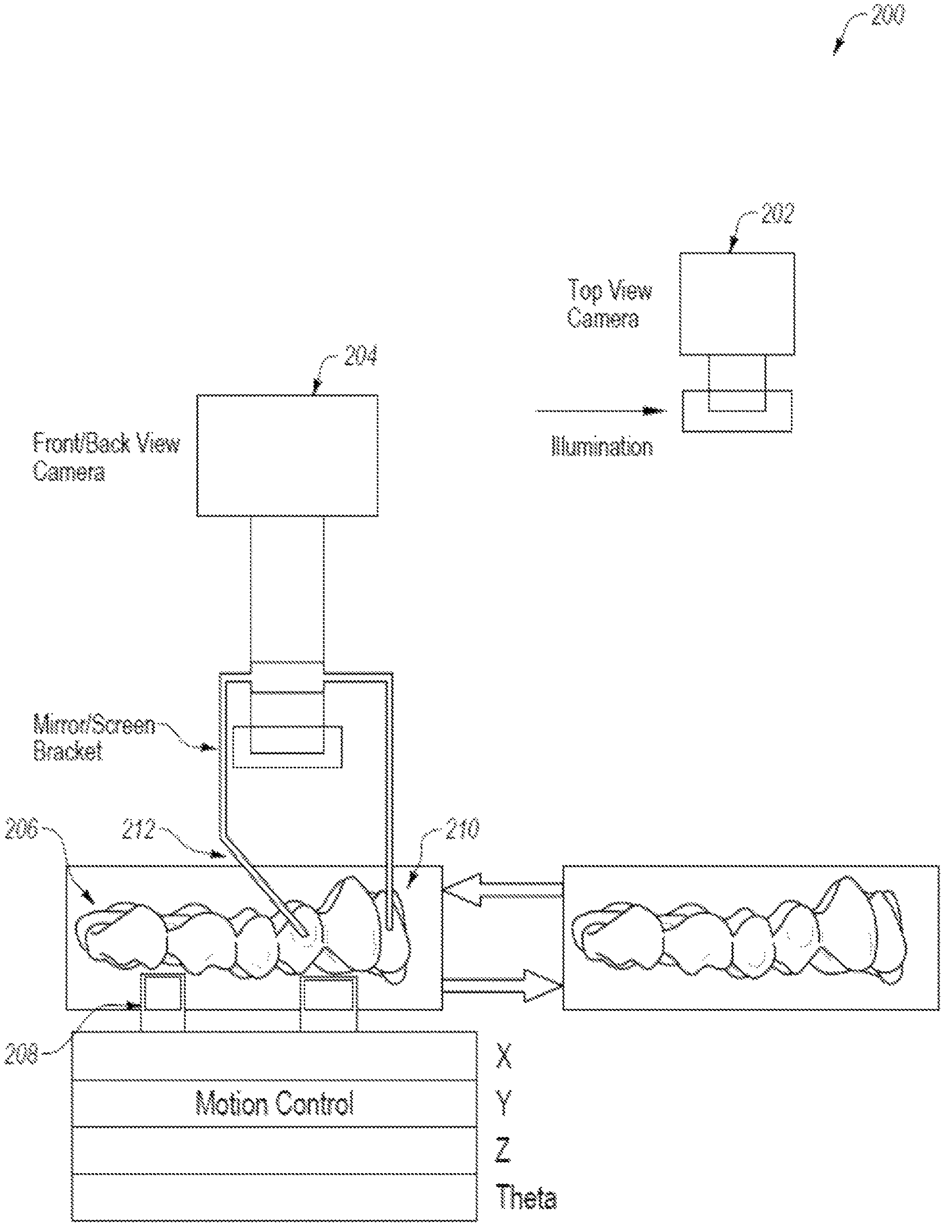
The hardware components could include a platform with either a rotating or fixed table for aligner positioning, image capture, camera setups (e.g. positioning) and/or lighting systems for uniform exposure and image acquisition with uniform ambient parameters. The hardware components can also be used to automate parts feeding (e.g. aligners) into the station. This will allow for image-based quality control and sorting at exit. One or more projections may show the images of an aligner. The hardware components can include a rotating or fixed table, as well as one or more cameras that allow for adjustable positioning. The configuration of the hardware components can be adjusted to allow for aligner images to be taken from various angles, such as top view, side view or diagonal view. One implementation may have a first camera that captures a top view of the aligner being analysed. A second camera can be set up to capture either side-view or diagonal views based on settings. A blue laser scanner may be included in the hardware components. This includes a camera, background screen and lighting. The shell image can also be obtained using these components. The image may contain certain information, such as the second property. A blue laser can be used at a specific angle on the aligner to produce a blue light beam that is received by a camera and generates an image of the plasticshell. To extract desired information (e.g. a second property), depth information may be taken from the image. Robot-guided cameras may be included in the hardware. These cameras use a design file as a guide to the cameras and generate images about the aligner being analysed. The aligner’s edge/cutline may be shown in the image. An ultrasonic device may be included in the hardware to measure the thickness of the aligner. The ability to measure the thickness of an aligner may allow for the formation of a quality trending analysis as well as detection of defects related to thickness. A stereo image sensor may be included in the hardware to capture a 3-D (3D) image. A confocal microscope may be included to obtain images of the aligner at different focal depths. An X-ray machine may be included in the hardware to scan the clear aligner at different cross-sections and take an image of it. You may use certain current and voltage settings to scan the clear plastic alignmenter cross-sections and get the image.
Some embodiments will be discussed with reference to aligners (also known as aligners). But embodiments can also be applied to other types shells that are placed over molds such as orthodontic retainers and orthodontic splints. Shells that are not dental applications. You may also find other applications when you inspect removable surgical fixation and removable mandibular positioning devices. It is important to understand that the embodiments that are described herein can also be applied to other types dental appliances. The principles, features, and methods described herein can be applied to any type of custom device, including eyeglass frames, contact lenses, hearing aids or devices, ortho inserts, prosthetic limbs, limbs and devices, knee guards, elbow, chin and shin protectors.
In certain embodiments, a mold may be made of the patient’s dental arch and a shell may then be created over it. Processing logic from a computing device may be used to fabricate the mold, such as FIG. 21. Processing logic can include hardware (e.g. circuitry, dedicated logic or microcode), as well as software. Software (e.g. instructions executed by a processor device), firmware, and other components may be included in the processing logic. A processing device that executes a computer-aided drafting module (CAD) program, for example, may perform one or more operations.
A treatment plan is used to determine the shape of a dental arch that a patient will need at each stage. An intraoral scan of the dental arch that will be modelled may be used to generate the treatment plan in orthodontics. An intraoral scan of a patient’s arch can be used to create a 3D virtual model (mold) of their dental arch. To generate 3D virtual models of the patient’s dental arch (mold), a complete scan of the maxillary and mandibular arches may be done. An intraoral scan can be done by creating multiple interrelated intraoral images from different scanning stations, and then stitching the intraoral images together to create a composite 3D virtual model. Virtual 3D models can also be created based upon scans of the object to model or computer-aided drafting techniques. An initial negative mold can also be created from an object that is already modeled (e.g. a dental impression, or similar). To determine the shape of the positive mold, the negative mold can be scanted.

A virtual 3D model of a patient’s dental arch can be generated by a dentist to determine the desired treatment outcome. This includes final positions or orientations. The treatment steps can be determined by processing logic. These stages will allow the teeth to move from their initial positions and orientations to their final positions and orientations. Calculating the progression of tooth movement during orthodontic treatment, from initial tooth placement/orientation to final corrected tooth positioning and orientation, can determine the shape of each final virtual 3D 3D model as well as each intermediate virtual model. A separate virtual 3D model may be created for each stage of treatment. Each virtual 3D model may have a different shape. Each virtual 3D modeling, including the original and final virtual models, is unique and personalized to each patient.

Click here to view the patent on Google Patents.