Invented by Jason How-Ring Ethier, Ivan Wang, German Lakov, Dynamo Ip Holdings LLC, Dynamo Micropower Corp
DC link level control refers to the management and optimization of fuel flows in power generation systems that utilize direct current (DC) links. These systems are commonly used in renewable energy sources such as solar and wind power, as well as in hybrid power plants that combine multiple sources of energy.
One of the key advantages of DC link level control is its ability to improve the overall efficiency of power generation systems. By carefully monitoring and adjusting the fuel flows, operators can ensure that the energy produced is maximized while minimizing waste. This not only reduces the environmental impact of power generation but also helps to lower operational costs for energy companies.
Another benefit of DC link level control is its ability to enhance the stability and reliability of power generation systems. By continuously monitoring the fuel flows, operators can quickly identify and address any issues or imbalances that may arise. This helps to prevent equipment failures and downtime, ensuring a consistent and uninterrupted supply of electricity.
The market for control of fuel flows at the DC link level is driven by several factors. Firstly, the increasing demand for renewable energy sources has led to a surge in the installation of solar and wind power plants. These plants require efficient control systems to optimize the utilization of the available resources and maximize energy production.
Secondly, the growing focus on energy efficiency and sustainability has prompted energy companies to invest in advanced control technologies. DC link level control systems offer a high level of precision and flexibility, allowing operators to fine-tune the fuel flows based on real-time data and changing conditions. This enables them to achieve optimal performance and reduce the carbon footprint of power generation.
Additionally, government regulations and incentives aimed at promoting clean energy have further fueled the demand for control systems at the DC link level. Many countries have implemented renewable energy targets and carbon reduction goals, which require energy companies to adopt more efficient and sustainable practices. As a result, the market for DC link level control is expected to experience significant growth in the coming years.
In conclusion, the market for control of fuel flows for power generation based on DC link level is a promising sector in the energy industry. With the increasing adoption of renewable energy sources and the growing emphasis on energy efficiency, the demand for advanced control systems is on the rise. By optimizing fuel flows and improving the overall efficiency of power generation systems, DC link level control plays a crucial role in the transition towards a cleaner and more sustainable energy future.
The Dynamo Ip Holdings LLC, Dynamo Micropower Corp invention works as follows
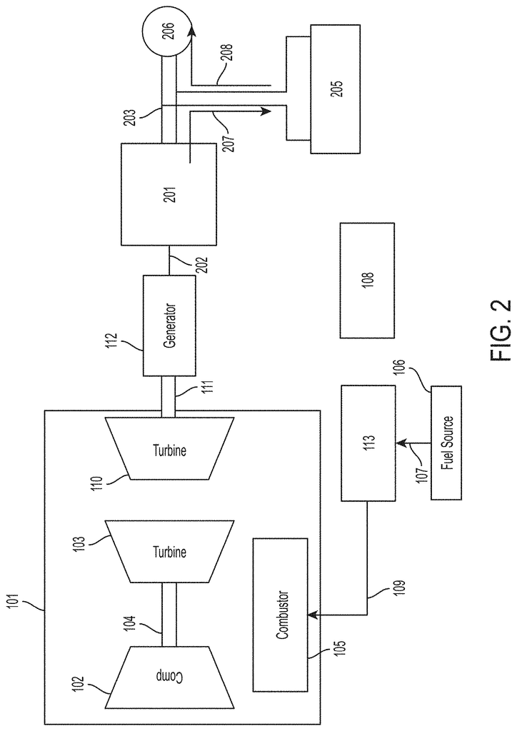
A power-generating unit, control module and modular power-generating system. The power generating system includes a motor-generator unit, which consists of an engine producing mechanical power and a mechanically coupled generator. The generator converts mechanical power into electrical power that is provided to a DC Link. The control unit contains at least one controller that controls fuel flow to an engine according to a DC link voltage.
Background for Control of fuel flows for power generation based DC link level
A power generating unit can generate electric power to be used in a wide range of applications. Power generating units can be used to generate primary power for residential, commercial or industrial purposes. A power generating system can be a diesel reciprocating motor connected to an electrical generator. The engine rotates the generator by generating shaft power. Generators provide electric power. The generator may condition the power by using AC-DC Converters or variable frequency drives before supplying the power to a load.
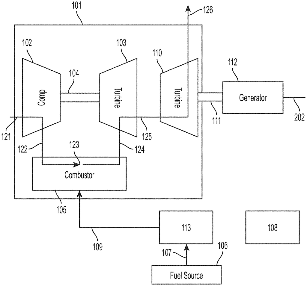
Another example of a power-generating unit is a gas turbine coupled with an electric generator. The generator’s electric power can be further processed, such as by AC-DC Converters, DC AC Converters or variable frequency drives.
A power generating unit comprising an engine-generator unit comprising an engine that generates mechanical power, and a generator that is coupled to the motor, wherein the power generator receives mechanical power and converts it to electrical power in a form that can be used by the energy storage unit.
The power generating device may also include a power delivery module that converts the DC link’s second electrical form into a third electrical form and outputs this third electrical form as an output from the power generating system.
The engine that generates mechanical power could be a gas-turbine engine.
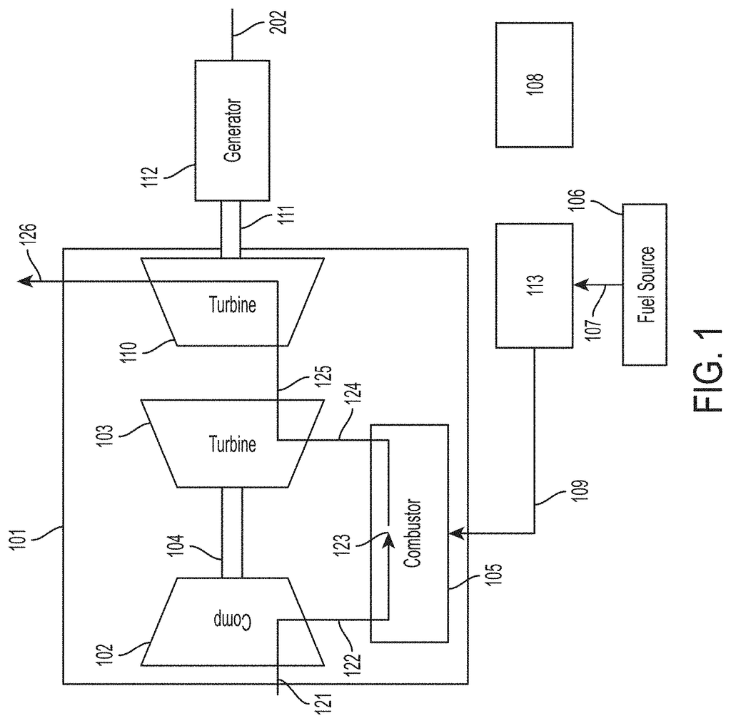
The gas turbine engine can be a two shaft gas turbine engine that includes: a compressor, a first turbo that is mechanically connected to the compressor and a second turbo that is not mechanically attached to the compressor or the first turbine. Gas from the first engine flows through the second and rotates the turbine to produce mechanical power.
The engine that generates mechanical power could be a reciprocating motor.
The generator that is mechanically connected to the engine can produce AC electrical energy and the first converter can convert it to DC electrical electricity which is supplied to the DC link.
The first power converter could be an AC-DC Converter.
A power delivery unit can convert DC electrical energy from the DC link in order to supply one or multiple loads.
The power delivery unit could be a DC to AC converter.
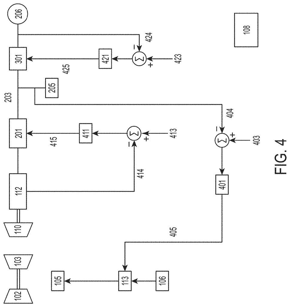
The control unit of a power generator unit that includes an engine-generator unit with an engine producing mechanical power, and a generator mechanically connected to the motor, in which the generator converts mechanical power into electrical power supplied to a DC Link, comprises: At least one controller configured for controlling fuel flow to engine based on voltage from the DC Link.
The at least one control can control the fuel flow into the engine through a fuel valve by commanding an initial set point.
The at least one controller can be at least part of a control circuit, wherein the loop gets a signal that represents a voltage on the DC Link; commands a setpoint to the fuel system of an engine based upon the signal representing voltage of DC Link; and maintains voltage of DC link in a range of specified values.
The at least one control may consist of at least a part of a plurality control loops. A first control circuit obtains a signal indicating a DC link voltage, a command to set an engine speed, and a control loop that maintains this voltage within a range of values. And a second loop which obtains the set engine speed, commands a setpoint for the fuel system, and maintains engine speed at setpoint commanded by first control.
The at least one control unit may be configured to control power from the generator and deliver it to the DC link in order to regulate the speed of the generator, or control power from a power supply unit and deliver it to a load in order to regulate the voltage of power delivered to that load.
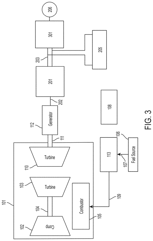
The modular power generation system consists of: two or more engines-generator units, each producing a different form of electricity; first converters, consisting of a converter for each engine generator set, configured to receive the first electrical power produced by its engine-generator unit and convert it to a second electrical power form; a DC-link that receives second electrical power generated by the first converters; an Energy Storage Unit that receives second electrical power via the DC-link; and at the least one controller that controls fuel flow based on voltage voltage, based on the DC-electrical power, a DC-generator a a a a DC- a a a a a a a a a a a a a a a DC- a a a a a a a a a –
The modular power generation system may also include one or more power units that are configured to receive the DC link’s second electrical form, convert it to a 3rd electrical form, and then provide this third electrical form as one or multiple outputs.
At least one of these engine-generator units may contain a gas turbine.
At least one of these engine-generator units may include a two-shaft turbine engine that includes: a compressor, a first turbo that is mechanically connected to the compressor and a second non-mechanically-connected turbine. Gas from the first turbine is fed through the second and rotates it to produce mechanical energy.
At least one engine-generator set may contain a reciprocating motor.
Click here to view the patent on Google Patents.

