Invented by Chen-Yi Liang, Yao-Tsung Chang, Wistron Corp
One of the key factors driving the growth of this market is the increasing popularity of VR gaming. As the gaming industry continues to evolve, gamers are seeking more immersive experiences that can transport them into virtual worlds. Adjustable VR devices allow gamers to adjust the display modules to optimize their field of view, resolution, and refresh rate, enhancing their gaming experience and making it more enjoyable.
Another significant driver for the market is the rising adoption of VR in various industries such as healthcare, education, and training. Adjustable VR devices enable professionals in these fields to customize the display modules to suit their specific needs. For example, in healthcare, surgeons can adjust the display to enhance their precision during virtual surgeries, while educators can optimize the display for immersive virtual classrooms.
Furthermore, the market for adjustable VR devices is also being fueled by advancements in display technology. Manufacturers are constantly innovating and introducing new display modules with higher resolutions, wider field of view, and faster refresh rates. Adjustable VR devices allow users to take full advantage of these advancements by fine-tuning the display modules to their liking, ensuring a more realistic and immersive experience.
Moreover, the market for adjustable VR devices is witnessing a surge in demand due to the increasing availability of content and applications. With more developers creating VR experiences, users are seeking devices that can provide them with the flexibility to enjoy a wide range of content. Adjustable VR devices allow users to optimize the display modules for different types of content, whether it’s gaming, movies, or virtual tours, ensuring an optimal experience every time.
In terms of market competition, several companies are already offering adjustable VR devices capable of adjusting display modules. These devices come in various forms, including headsets, goggles, and glasses, catering to different user preferences. Some companies are also integrating eye-tracking technology into their devices, allowing for even more precise adjustments based on the user’s gaze.
As the market for adjustable VR devices continues to grow, manufacturers are also focusing on improving the comfort and ergonomics of these devices. Ensuring a comfortable fit and reducing the weight of the device is crucial for prolonged VR sessions. Additionally, advancements in wireless technology are also being incorporated into these devices, eliminating the need for cumbersome cables and enhancing the overall user experience.
In conclusion, the market for adjustable VR devices capable of adjusting display modules is experiencing significant growth due to the increasing demand for immersive and customizable virtual experiences. With the rising popularity of VR gaming, adoption in various industries, advancements in display technology, and the availability of diverse content, these devices offer users the flexibility to fine-tune their VR experience, resulting in a more enjoyable and realistic virtual environment. As the market continues to evolve, manufacturers will continue to innovate and improve these devices, ensuring a bright future for adjustable VR technology.

The Wistron Corp invention works as follows
An adjustable virtual-reality device includes a display module with a display unit and an image capture unit. It also has a driving unit for lateral movement, as well as a control unit. The first and second display modules display a respective first and second image. The first and second image capturing units detect the two positions of pupils on two eyeballs. The control unit calculates the distance between two pupils based on the two positions and then controls the lateral driving modules to drive the first and second display modules in a sideways direction. This increases comfort during use.

Background for Adjustable Virtual Reality Device capable of Adjusting Display Modules
1. “1.
The present invention is a virtual-reality device and, more specifically, an adjustable virtual-reality device that can adjust display modules.
2. “2.
A virtual-reality device uses two displays to provide images for the two eyes of a person in order to create a 3-dimensional effect through binocular disparity. The positions of the two displays in a virtual reality device conventionally cannot be adjusted to match the pupil distance between a user’s eyes. It can easily cause dizziness or discomfort. Another conventional virtual reality device is capable of manually adjusting the distance between two displays to reduce discomfort. Since the users adjust the distances between two displays based on visual feelings, it is not possible to match the pupil distance of two user’s eyes exactly. This causes discomfort when the virtual reality device is worn for a short time. The distance between two displays, two eyeballs, or two glasses lenses is not adjustable. Two displays can easily interfere with the eyeballs and lenses of the virtual reality device when the user is wearing it. This causes discomfort. It is also not possible to customize the device for users with a high binocular dispersion.
The present invention aims to solve the problems by providing an adjustable virtual-reality device that can be adjusted with display modules.
The present invention discloses a virtual reality adjustable device that can adjust display modules in order to achieve this objective. The adjustable virtuality device includes a base, housing, first display module with a first detecting module, second display module with a second detection module, at least one driving transverse module and a controller. The base is located inside the housing. The first display module can be moved on the base to display a first picture. The first detecting unit includes a capture module for a primary position of the first pupil in a single eyeball. The second display module can be moved on the base to display a second picture. The second detecting unit includes a capturing module for detecting the second position of an eyeball’s second pupil. The at least transverse driving modules are used to drive the first display module or the second display module in a transverse motion. The control unit is electrically linked to the atleast one transverse module, the first and second image capturing units. The control unit controls at least one transverse module in order to drive the display modules to move independently or synchronously according to the relation between the pupils based on the position of the pupil of the first and second displayed module detected by the image capturing module.
The present invention discloses a virtual reality device that can be adjusted to adjust display modules in order to achieve this objective. The adjustable virtuality device consists of a housing, base, first display module with a first detecting unit, second display module with a secondary detecting unit, longitudinal driving module and control unit. The base is located inside the housing. The first display module can be moved on the base to display a first picture. The first detecting module includes a distance-detecting unit that detects a distance between the display module of the first eyeball and a lens or glasses matching a second eyeball. The second display module can be moved on the base to display a second picture. The second detecting module includes a distance-detecting unit that detects a distance between the second display module, a lens corresponding to a secondary eyeball and a distance between the second display modules. The longitudinal driving unit is used to drive the first and second display modules in a longitudinal direction. The control unit is connected electrically to the longitudinal drive module, first distance detecting units, and second distance detecting units. The control unit drives the longitudinal driving module so that the first display and second display modules move in the longitudinal direction according a reference distance generated from the first distance and second distance.
The adjustable virtual reality device uses the first and second image capture units to detect the two positions where the first and second pupils of the eyeball are located. It then controls the transverse driving unit to drive the display modules to move in the transverse direction based on the distance between the eyeballs of the eyeballs of the eyeballs of the eyeballs of first and second pupils or the positions between the eyeballs of first and second pupils. This allows for the transverse distance of the display modules to correspond to the distance between them It increases comfort when using. The adjustable virtual reality device of this invention also uses the first and second distance detecting units to detect the distances between the display modules and the eyeballs or lenses of the glasses that correspond to the eyeballs, as well as the distances between the display modules and second eyeballs or second lenses of the glasses that correspond to the eyeballs, and then controls the longitudinal driving unit to drive both the display modules to move in the longitudinal direction based on the distances. This prevents the display modules from interfering either with the It also increases comfort when used.
The following detailed description of preferred embodiment, illustrated in various figures and drawings, will make it clear to anyone with ordinary knowledge of the art what the objectives of this invention are.
In the detailed description of preferred embodiments that follows, references are made to the accompanying illustrations which form part of this document and which illustrate specific embodiments where the invention can be implemented. In this respect, directional terms such as “top”,? ?bottom,? ?front,? ?back,? The term etc. is used to refer to the orientation of a figure. Components of the invention can be positioned at different angles. The directional terminology used is for illustration purposes only and not to limit. The drawings and descriptions are therefore viewed as illustrations and not restrictive.

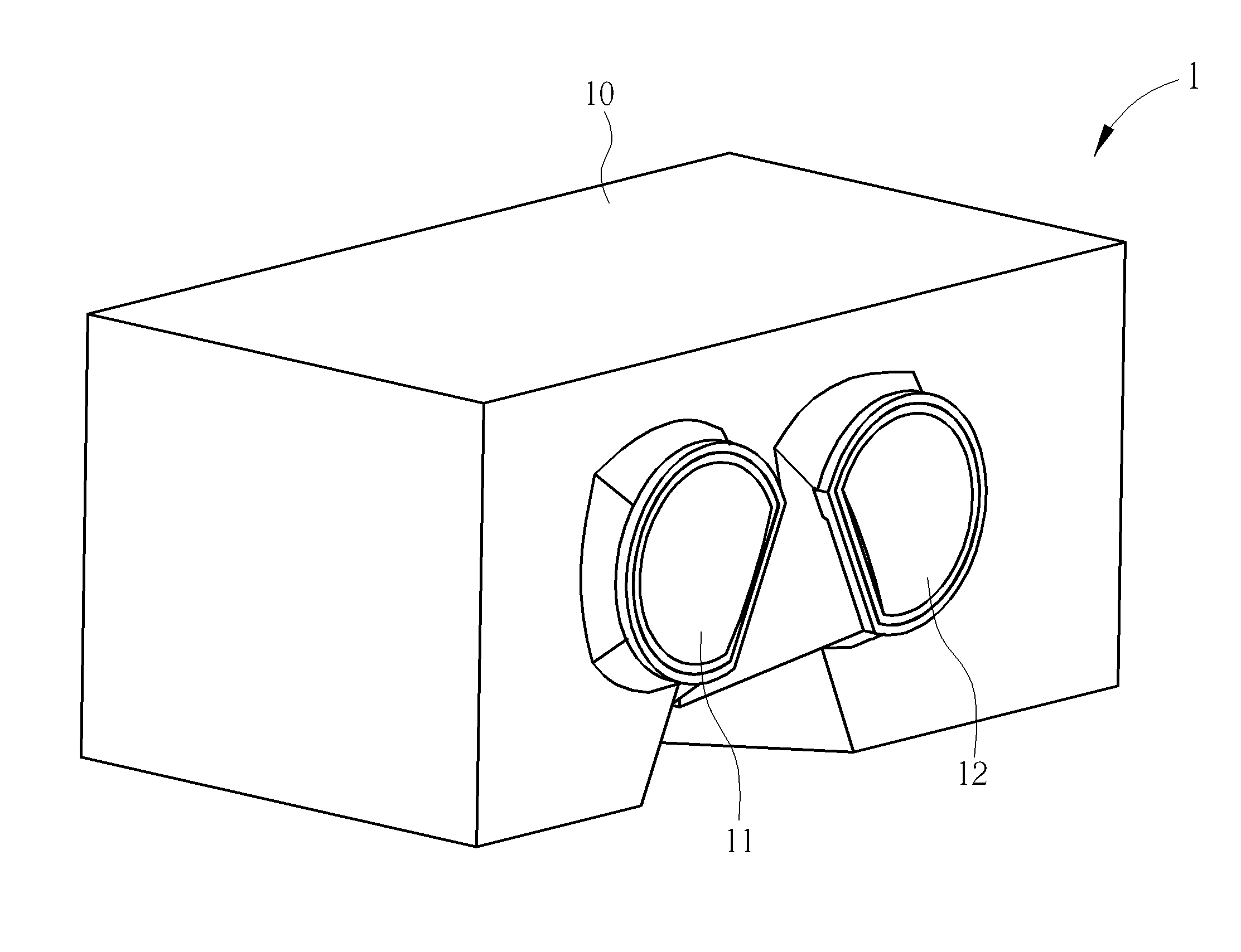
Please refer to FIG. Refer to Figure 1 3. FIG. FIG. 1 is a diagrammatic representation of a virtual reality device that can be adjusted according to the first embodiment of this invention. FIG. FIG. 2 shows an exploded view of the virtual reality device adjustable 1 in the first embodiment. FIG. FIG. As shown in FIG. As shown in FIG. The adjustable virtual reality device 1, which is shown in Figure 3, includes a housing, a first display unit 11, a second module 12, a display base 13, two driving modules 14, a transverse module 15, and a controller 16. The base 13 is located inside the housing 10. The base 13 is mounted on a movable display module 11, which displays a first picture. The second display 12 is movably placed on the base 13, and displays a second picture. The transverse driving unit 14 is mounted on the base 13, and electrically connected with the control unit 16, to drive the first display module 11, and the second display modules 12 along the transverse direction X. The two longitudinal modules 15 are electrically connected to control unit 16 and connected to base 13. They drive the first display module 11, and the second module 12, along a substantially parallel longitudinal direction Y to the transverse direction. The numbers of the transverse and longitudinal driving modules 14 and 15 are not restricted to this embodiment. It depends on the practical requirements. The adjustable virtual reality device 1, for example, can also include two transverse driving modules 14 and one longitudinal driving module 15. The longitudinal driving 15 can be located on a side of base 13. The two transverse drive modules 14 can also be mounted on the base 13, and connected to the first and second display modules 11 and 12, respectively, to adjust the positions of the two pupils in the two eyeballs.
The transverse driving modules 14 are composed of a screw rod transverse 140, a guiding rod transverse 141 and an assembly transverse motor 142. The transverse screw 140 is located on the base 13, and is arranged in a transverse direction (X). The transverse guiding bar 141 is parallel to the screw rod 140 and positioned on the base 13. The transverse screw 140 and transverse guiding 141 are mounted on the base 13 in a moveable manner along transverse direction X. The control unit 16 is electrically connected to and coupled with the transverse motor assembly. The control unit 16 drives the transverse screw bar 140, which then drives the first display module 11, and the second display modules 12 along the transverse direction. The transverse guiding bar 141 guides the display modules 11 and 12 along the transverse directions X, and prevents them from moving in the longitudinal direction when they move along transverse directions X. The transverse driving modules 14 do not have to be limited to the components and structures shown in this embodiment.
Each longitudinal driving module 15 comprises a longitudinal screw bar 150, two long-distance guiding rods, a motor assembly 152 and a control chair 153. The longitudinal screw 150 is located on the control seat and is arranged in longitudinal direction Y. On the control seat, the two longitudinal guiding struts 151 are parallel to the longitudinal screw strut 150. The two longitudinal guiding 151 are located between the longitudinal screw rod. The base 13 can be moved along the longitudinal Y direction by being positioned on the longitudinal screw 150 and two longitudinal guiding bars 151. The longitudinal motor assembly is mounted on the control seat, connected to the longitudinal screw bar 150 and electrically linked to the control unit 16 The control unit 16 drives the longitudinal screw bar 150, which in turn moves the base 13, along the longitudinal Y direction. The two longitudinal guiding bars 151 guide and restrict the base to move in the longitudinal direction. The longitudinal driving module 15 is not limited to the components and structures shown in this embodiment.
Please refer to Figure 3 and FIG. Refer to FIG. 4. FIG. The first display module 11, and the second module 12, according to the invention’s first embodiment, are shown in an exploded view. The first display module 11, which includes a lens assembly 112, a display component 111 and a shell 110, is composed of a display component 111. The base 13 is used to move the first shell 110. The first display component (111) is located inside the first shell 110 for the purpose of displaying the image. The first lens assembly is located on the first shell and used to enlarge the first image. First back cover 113 and first shell 110 are combined to cover internal components such as the display component 111. The second module 12 consists of a shell 120, second component 121 and a lens assembly 122. The second shell is movably mounted on the base 13 The second display component is located inside the second shell and displays the second image. The second lens assembly is located on the second shell and is used to enlarge the second image. The second backcover 123, which is combined with second shell 120 to cover internal components such as the display component 121.
Furthermore the adjustable virtuality device 1 includes a first detection assembly 17 and second detecting assemblies 18. As shown in FIG. As shown in FIG. The second detecting unit 18 is located inside the second shell of the display module 12, and at the opposite side of second component 121 from the lens assembly 122. The first detecting unit 17 and first lens assembly 112 is located on two opposite sides to the first display component, and the 2nd detecting unit 18 and second lens assembly 122 at two opposite side of the 2nd display component.
The first detecting assembly 17 consists of a distance detecting unit 171, a first image capture unit 170 and a partition plate 172. The first image capture unit 170, which is electrically coupled to the control module 16, detects a position of a pupil in a primary eyeball. The first distance detecting module 171 detects a distance between the display module 11 of the first eyeball, or the first lens of the user’s glasses, when the user is wearing the glasses. The first partition plate is used to receive the first distance-detecting unit 171 as well as the first image-capturing unit 170. The second detecting system 18 consists of a 2nd image capturing unit, a 2nd distance detecting unit and a 2nd partition plate. The second image capture unit 180 is electrically coupled to the control module 16 and detects a position of a pupil of a secondary eyeball. The second distance detecting module 181 detects a distance between the display module 12 of the second eyeball and a lens or second of the glasses that correspond to the eyeball. The second partition 182 receives the second distance-detecting unit 181 as well as the second image-capturing unit 180. The control unit 16 drives the transverse driving unit 14 to move the first display module 11, and the two display modules 12 along the transverse X direction according to the results detected by the first image capture unit 170, and the second image capture unit 180. The control unit 16 controls two longitudinal driving modules 15, which drive the first display unit 11 and the 2nd display module 12 along the longitudinal direction “Y” according to the results of the distance detecting units 171 and 181.
The first detecting unit 17 and the second detection assembly 18 are not restricted to this embodiment. In a different embodiment, either the first image-capturing unit 170 OR the first distance-detecting unit 171 can be included in the first detecting assemblies 17 and 18, respectively. The second detecting assemblies 18 can also only contain the second image-capturing unit 180 OR the second distance-detecting unit 181. The first distance detecting units 171 and 181 are not only limited to detecting first and second distances. In a different embodiment, the first unit can also be used to detect a diopter for the first eyeball and the second unit can also be used to detect a diopter for the second eyeball. The control unit 16 controls the two longitudinal driving units 15 to drive the display modules 11 and 12 along the longitudinal direction of Y in accordance with the diopters. This allows the first image to be clearly focused on the retina of a first eyeball of the first eyeball or a retina of a second eyeball of the other eyeball. The present invention allows a user who is farsighted or nearsighted to adjust the image positions of both the first and second images focused on the retinas based on diopters measured by the distance-detecting units. This allows the user to see clearly an image composed by the first and second images without glasses.
As shown in FIG. In this embodiment, because the first detecting assemblies 17 and 18 are located on the opposite side from the lens assembly 112 of the display component of the display component of the display component of the display component of the display component of the display component of the display component of the display component of a display component of a display component of 121 and away from it, respectively, they can be two transparent organic LED displays or two translucent liquid crystal displays. This allows the image capturing units 170 and 171 and second distance detecting units 180 and 181 in the second detecting assemblies 181 In another embodiment, however, the first component 111 and second component 121 can also be two nontransparent liquid-crystal displays. First detecting assembly 17 can detect first eyeball, and second eyeball using electron beams that penetrate through the non-transparent displays. “It depends on the practical requirements.
Desire not be limited by this embodiment, however the configurations of first detecting assemblies 17 and 18 can also vary. In a second embodiment, the first assembly 17 can also be located inside the shell 110 of the display module 11, on a side near the lens assembly 112 of the display component 111. The second detecting unit 18 can also be located inside the second shell of the display module 12, and at the side of the display component 121, near the lens assembly 122. The first detecting unit 17 and first lens assembly 112 can be located on the same side as the first display component. The second detecting unit 18 and second lens assembly are also located on the same side as the second display component. First image capturing assembly 170, first distance detecting component 171 and second image capturing 180 and second distance detecting 181 of first detecting assemblies 17 detect the first and second eyeballs by emitting and receiving light reflected off the first display component and second display component respectively. In another embodiment, a second detecting unit 18 can also be located near the edge of the display component of the second component. Software can repair parts of the first and second images that are shaded by first detecting assemblies 17 and 18. It depends on the practical requirements.
Please refer to Figure 3 and FIG. Refer to FIG. 5 and FIG. 7. FIG. The diagrams in FIG. Diagrams of the internal components of adjustable virtual reality device 1, in different states, according to the invention’s first embodiment. The housing 10 has been omitted in order to demonstrate the operation of the adjustable VR device 1 according to the present invention. The housing 10 is not shown in FIG. 7. The first image capture unit 170 detects the first position of a pupil in the first eyeball. The second image capture unit 180 detects the second position of a pupil in the second eyeball. The control module 16 calculates the distance between the first and second pupils based on the first and second positions and then controls the transverse driving unit 14 to move the first display module 11, and the 2nd display module 12, along the transverse X direction according to this pupil distance. The first display module 11 moves from the two positions in FIG. The first display module 11 and the second display module 12 move from two positions shown on FIG. The first display modules 11 and 12 are moved away from each other so that the transverse distance between them is equal to the pupil distance. This can prevent the user feeling dizzy or uncomfortable.

The two transverse modules 14 can adjust the first display module 11, and the display module 12, to positions that correspond to the positions of the pupil 170, and pupil 2 detected by the image capturing units 170, and 180, respectively.

Click here to view the patent on Google Patents.