Invented by Huaisong Zhu, Hugo Tullberg, Zhan Zhang, Telefonaktiebolaget LM Ericsson AB
Wireless communication systems have become an integral part of our daily lives. From smartphones to smart home devices, wireless connectivity has revolutionized the way we communicate and interact with the world around us. The market for wireless communication systems is expected to reach new heights in the coming years, driven by the increasing adoption of Internet of Things (IoT) devices, 5G technology, and the need for seamless connectivity.
Radio network nodes play a crucial role in wireless communication systems. These nodes act as the backbone of the network, facilitating the transmission of data between devices. With the advent of 5G technology, the demand for radio network nodes has surged. 5G networks require a dense network of nodes to ensure high-speed and low-latency connectivity. This has created a lucrative market for radio network node manufacturers, with companies investing heavily in research and development to meet the growing demand.
Machine learning units have also gained prominence in the wireless communication industry. Machine learning algorithms enable wireless communication systems to analyze vast amounts of data and make intelligent decisions in real-time. These units are capable of optimizing network performance, predicting user behavior, and enhancing security measures. The market for machine learning units is expected to witness substantial growth as wireless communication systems become more complex and data-driven.
When it comes to transmitting a downlink in wireless communication systems, several methods are employed. One of the most commonly used methods is Orthogonal Frequency Division Multiplexing (OFDM). OFDM divides the available frequency spectrum into multiple subcarriers, allowing for simultaneous transmission of data. This technique ensures efficient utilization of the available bandwidth and minimizes interference.
Another method for transmitting a downlink is Multiple Input Multiple Output (MIMO) technology. MIMO utilizes multiple antennas at both the transmitter and receiver ends to improve data throughput and enhance signal quality. By transmitting multiple data streams simultaneously, MIMO technology enables faster and more reliable downlink transmission.
Furthermore, advancements in beamforming techniques have revolutionized downlink transmission. Beamforming allows wireless communication systems to focus the transmission in a specific direction, thereby increasing signal strength and reducing interference. This technology is particularly beneficial in urban environments where signal propagation can be challenging.
In conclusion, the market for wireless communication systems, radio network nodes, and machine learning units is witnessing rapid growth. With the proliferation of IoT devices and the advent of 5G technology, the demand for efficient and reliable wireless connectivity is at an all-time high. Manufacturers are investing in research and development to meet these demands and capitalize on the market opportunities. Additionally, advancements in downlink transmission methods such as OFDM, MIMO, and beamforming are further enhancing the performance and reliability of wireless communication systems. As technology continues to evolve, the wireless communication market is poised for even greater advancements in the future.

The Telefonaktiebolaget LM Ericsson AB invention works as follows
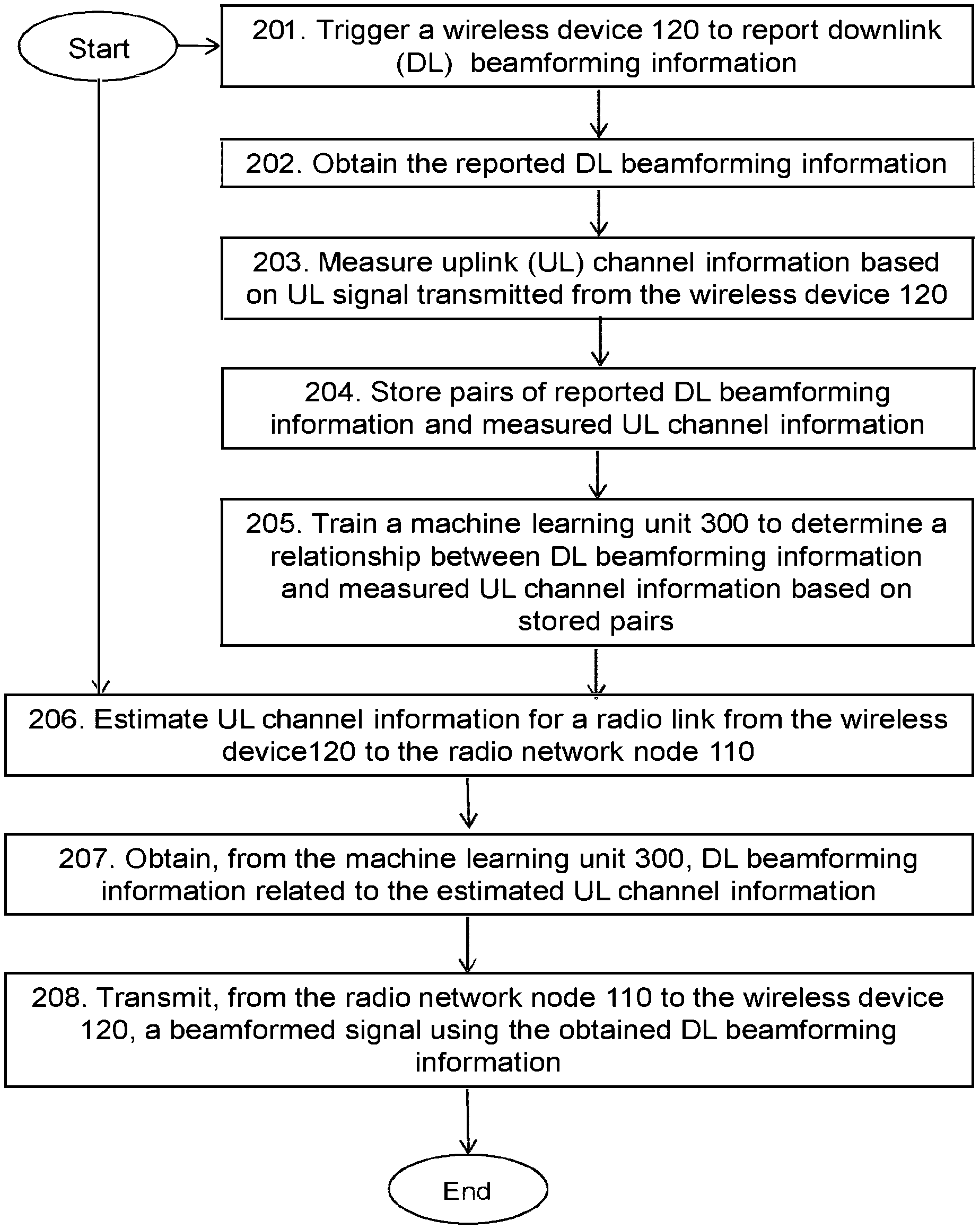
A wireless communication system and method for transmitting a downlink in a wireless network that supports beamforming.” The system estimates the uplink channel for a radio connection from a wireless device towards a node of a radio network. A machine learning unit provides downlink beamforming data based on the estimated uplink information. The machine learning unit consists of relationships between beamforming and uplink information, determined by stored pairs of measured uplink information and reported downlink information. The downlink beamforming data is suitable for the radio-cell sector. The system also transmits a downlink signal beamformed using the downlink beamforming data towards the wireless device.

Background for Wireless communication system, radio network node and machine learning unit, as well as methods for transmitting a downlink in a wireless communication network supporting beam-forming
In a typical wireless network, wireless devices (also known as wireless communication device, mobile stations, station (STA), and/or user equipments (UEs) communicate via a Local Area Network, such as a WLAN network or a Radio Access Network, to one or multiple Core Networks. The RAN is a geographic area that can be divided into service or cell areas. These areas may also refer to as a “beam” or a “beam group”. Each service or cell area is served by a Radio Network Node, such as a Radio Access Node, e.g. a Wi-Fi or a Radio Base Station, or gNB in 5G. The radio network node provides radio coverage in a service area, or cell area. The radio network communicates with wireless devices within the range of the node using an air interface that operates on radio frequencies.
The 3GPP has completed the specifications for the Evolved packet System (EPS), or Fourth Generation (4G) Network. This work will continue in future 3GPP releases to include, for instance, a Fifth Generation network (also known as 5G New Radio) (NR). The EPS consists of the Evolved Terrestrial Access Network (E-UTRAN), which is also known by the name Long Term Evolution radio access network (LTE), and the Evolved packet core (EPC), or System Architecture Evolution core network (SAE). E-UTRAN/LTE, a 3GPP variant radio access network, is a variation where the radio network nodes directly connect to the EPC network core instead of the RNCs that are used in 3G networks. E-UTRAN/LTE is a variant of 3GPP radio access network where the radio nodes are directly connected to the EPC core network rather than RNCs used in 3G networks. In LTE there are eNodeBs and the core network. The RAN in an EPS is essentially “flat”. The RAN of an EPS has a?flat?architecture, with radio network nodes directly connected to one or several core networks. They are not connected to RNCs. The E-UTRAN specification provides a direct interface that is called the X2 Interface to compensate for this.
Multi-antenna systems (AAS) are able to increase data rates and reliability in wireless communication systems. Performance is improved when both the transmitters and receivers are equipped with multiple-antenna systems, resulting in a Multiple Input Multiple Output (MIMO), communication channel. MIMO is a term used to describe such systems or related techniques.
In addition, 5G plans aim to increase capacity over current 4G. This will allow for a higher number of mobile users per area unit and more data consumption per user or per gigabyte. It would be possible for many people to stream high definition media on their mobile devices even when they are not within range of Wi-Fi hotspots. The 5G research and developments also aim to improve support for machine-to-machine communication, or the Internet of things. They also aim at lower costs, lower battery consumption, and lower latency compared to 4G equipment.
The development of the next-generation wide area communication networks is underway. Next generation wide area networks can be referred as NeXt Generation (NX), NR, or 5G. The ultra-lean concept is a design principle that will be used for the 5G wireless communications networks. The design principle is to avoid ‘always-on signals’, like the LTE reference signals, as much as possible. This design principle is expected to have a number of benefits, including: Significantly lower network energy consumption. Better scalability. Higher degree of forward compatibility. Lower interference from system overhead signal. Higher throughput for low load scenarios. The term “wireless device-centric beamforming” is used. It means that beamforming is chosen based on the needs or requirements of the wireless device.
The technology in advanced antenna systems has improved significantly over the past few years. A rapid technological development is expected in the coming years. In the future, wireless networks will use advanced antenna systems and massive MIMO transmissions and receptions.
The same technique can be used for reception. “A beam” is typically associated with transmission, using beamforming. As a technique of signal processing, beamforming or spatial filtering can be used for directional transmission and/or receipt. It is usually achieved by combining the elements of a phased antenna array (also known as a phased-array) in a way to cause constructive interference for certain angles, while causing destructive interference for others. The beamforming technique can be applied at both the receiving and transmitting ends to achieve spatial selection. Thereby, thanks to directivity, improvements are possible to achieve compared with omnidirectional reception/transmission. A transmitter can perform transmit beamforming, for example, by transmitting the exact same signal to all elements of a Phased Array, with an exception of a weight per element consisting of a phase shift factor and amplitude factor. A receiver, with a phased array that can be configured the same as the transmitter’s, can perform receive beamforming using the per-element weights. Transmission and reception can both have the same selectivity and directionality. It means the signal is stronger in one direction and weaker elsewhere. Receiving signals means that some directions or directions will be amplified, while others are attenuated. It is possible to use the same antenna, i.e. The same antenna can be used for both transmission and reception, although not usually at the same time.
Beams or beamforming can be used in both the uplink and downlink. They may also be used at either one end of communication, or at both. In the case of a wireless network communicating with a communication device in the downlink, the wireless network could use transmit beamforming, and/or the device could use receive beamforming. In the same way, when a wireless network is communicating with a device via the uplink, the wireless network can use receive beamforming, and/or the device can use transmit beamforming. The synonyms for transmit beamforming are transmission beamforming, transmitting beamforming, and the synonymous names for receive beamforming are reception beamforming, or receiving beamforming. When referring to a “beam”, a transmit beam (i.e. A radio beam that is formed or generated using transmit beamforming. As can be seen from the above, receiving beams can also make sense. Receiving beams are associated with beams. Herein, ?beam? If nothing else is mentioned,?beam? usually refers to the transmit beam.
A network node typically provides a beam for communication, such as with a cell phone. For serving one or few communication devices (compared to cell) at the same time and may be set up specifically for communication with them. By beamforming, the beam can be dynamically changed to cover a single or a few communication devices using e.g. The beam is used to serve the target. “A beam is usually provided by a device for communication with a wireless communication network. Specifically, one or several radio network nodes, and in particular one or more that are the main targets for the beam.
A transmit beam can be assigned one or more identifiers, and/or identities. These may be fixed and/or dynamically allocated. There can be the same identifiers or identities for a group of beams. Multiple beams, e.g. All of the multiple beams are mapped to the same cell identity, e.g. There may be multiple beams within a single cell and/or others that are used to identify a specific beam. An individual beam in a group or cell of beams. The beam can be identified by a beam identifier or beam identity. The beam identifier and/or beam identity may be directly identified by the beam. By referring to the frequency and/or time of a reference signal received transmitted using that beam.

Beamforming can improve performance by improving both the coverage and the signal strength received. Beamforming can be used in both the transmitter and receiver of a wireless device or radio network node. In a receiver, beamforming can be configured to only receive signals from a certain direction or few directions. In a transmitter, beamforming can be configured to receive only signals in a specific direction or few directions and not other directions. The beam pair can be used to refer to the beams that are selected at both ends when beamforming is implemented in both the transmitter as well as the receiver of a communication link. The beamforming gains depend on the beam widths. A narrower beam will provide more gain than a larger beam.
The 5G networks support massive MIMO, which is a very high-grade form of spatial transmission and processing.
To support beamforming in massive MIMO, 3GPP defines an extremely complex codebook, consisting of hundreds of Precoder Matrix Indicators (PMIs). The 3GPP defines, for example, a list of pre-coders. Vectors are collected in a “code-book”. The 3GPP also assigns each pre-coder a unique integral number that ranges from zero to tens of hundreds. The standard refers to the integral number as PMI.
Each precoder can be mapped to a specific direction and phase between polarizations. The wireless device that is in the same phase as the polarizations will send the PMI to the eNB. The eNB can be, for example. The gNB follows wireless devices’ reports and beamforms transmissions in order to send the signal in the desired direction with the correct phases of polarizations.
An alternative beamforming method is based on uplink measurements. In a Time Division Duplex-based communication system, UL signals and DL signal are transmitted in adjacent time slots on the same carrier. The eNB can assume that the uplink channel measured by the eNB is the same as the DL channels, and the beamforming precoder for the DL channels may be selected or calculated based on the eNB measurement of the UL channels. This is what is known as a ‘channel reciprocity-based method’, sometimes referred to in this disclosure as ‘an eNB measurement-based DL beamforming. In contrast to wireless device measurements and reports based on DL Beamforming.
According to the development of wireless communication systems, an improved beamforming method is required for the improvement of the wireless system’s performance.
Therefore an object of embodiments is to overcome, among other things, the drawbacks above-mentioned and to improve performance in a Wireless Communications System.
According to one aspect of embodiments, the object can be achieved by a technique performed in a system of wireless communication for transmission of a signal downlink in a network of wireless communications supporting beamforming.
The system estimates the uplink channel for a radio connection from a mobile device to a node of the radio network, when the mobile device is within a radio-cell sector in the wireless communication network.
Further the system obtains estimated uplink channel and downlink beamforming data from a machine-learning unit. The machine learning unit consists of relationships between beamforming and uplink information, determined by stored pairs based on reported downlink beamforming and measured uplink information. The downlink beamforming data is useful for the radio-cell sector.

Furthermore the system transmits from the radio node to the wireless device a beamformed signal downlink using the downlink beamforming data.

Click here to view the patent on Google Patents.