Invented by Yunjun Li, Richard Lee Fink, Mohshi Yang, Zvi Yaniv, Applied Nanotech Holdings Inc
The oil and gas industry is a significant contributor to the global economy, and the demand for oil and gas is expected to increase in the coming years. This growth in demand has led to an increase in the exploration and production of oil and gas, which, in turn, has driven the market for well formation.
The market for well formation is highly competitive, with many companies offering a range of services and products. The competition is driven by the need to provide cost-effective solutions that meet the specific needs of the oil and gas industry. Companies that offer innovative solutions and services that improve the efficiency of well formation are likely to gain a competitive advantage.
Drilling equipment is a crucial component of the well formation market. The drilling equipment market includes various types of equipment, such as drill bits, drilling rigs, and drilling fluids. The demand for drilling equipment is driven by the need to drill deeper and more complex wells. The development of new drilling technologies has also contributed to the growth of the drilling equipment market.
Well completion tools are another critical component of the well formation market. Well completion tools are used to complete the wellbore and prepare it for production. The well completion tools market includes products such as casing, tubing, and packers. The demand for well completion tools is driven by the need to improve the efficiency of well completion and reduce the time and cost of completing a well.
Well stimulation services are also an essential component of the well formation market. Well stimulation services are used to improve the productivity of the well by increasing the flow of oil or gas. The well stimulation services market includes products such as hydraulic fracturing and acidizing. The demand for well stimulation services is driven by the need to improve the productivity of existing wells and increase the recovery of oil and gas.
In conclusion, the market for well formation is a growing industry that plays a critical role in the oil and gas sector. The demand for oil and gas is expected to increase in the coming years, which will drive the growth of the well formation market. Companies that offer innovative solutions and services that improve the efficiency of well formation are likely to gain a competitive advantage in this highly competitive market.


The Applied Nanotech Holdings Inc invention works as follows
Inks made from carbon nanotubes can be dispensed via inkjet deposition or other methods. The CNT ink dispensed is into cathode-shaped wells. Inks are made up of carbon nanotubes and binding materials. Other nanoparticles may also be present. Binding materials can include epoxies, silicates and other materials.


Background for Well formation
Cathode homogeneity is critical for the commercialization of field emission displays.” The highest potential is found in carbon nanotubes (CNT) as cathode material for future field emission displays. One of the most challenging aspects of FED fabrication is to deposit CNTs uniformly and selectively over a large surface. Chemical vapor deposition techniques (CVD) with catalyst activation are a typical way to grow carbon nanotubes onto a substrate. This technique is expensive because it requires a high temperature for growth. A film that has uniform properties across a large surface is difficult to produce. CNTs can be deposited in composites using other methods such as screen printing or dispensing. Composites are made of CNT powder, which is mixed with other particles such as conductive or not-conductive particles. They can also contain carriers or vehicles or binders. These techniques create patterns that are not uniform from one spot to another, resulting in non-uniform emitting areas for each pixel. The edge emission of CNT composite paste or ink can also cause non-uniformity in the CNT cathode’s performance.
For FED application, depositing the exact same amount of CNTs onto each pixel and sub-pixel to achieve uniform emitting areas is a key goal in order to obtain uniform emission currents from an individual pixel. CNT deposition should be the final step of the cathode manufacturing procedure, particularly for triode structures. “Once a CNT is prepared, any further wet chemical processes or etching that could degrade cathode performance shouldn’t be applied on the surface.
In the following description numerous specific details will be provided to give a complete understanding of the invention. It will be evident to those in the know that the invention can be implemented without these specific details. “In other cases, well-known circuits are shown in block diagram format to avoid obscuring the present invention with unnecessary details.
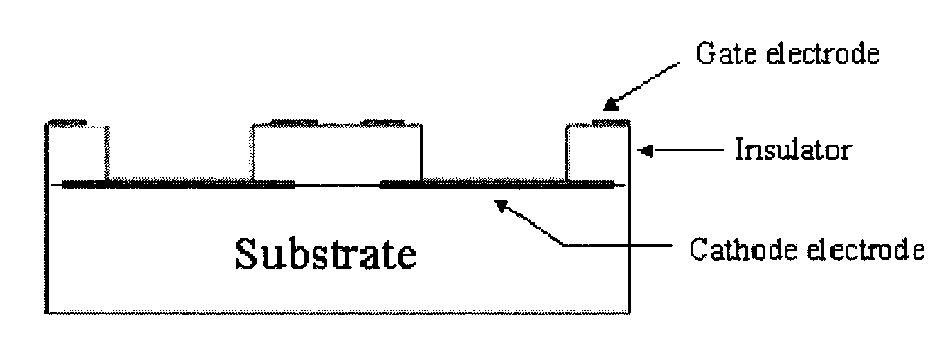
An embodiment provides a method for uniformly depositing the CNTs in well structures, as shown in FIG. 1( a). Well structures can have four or more walls that form a hole, (or just one wall for a round hole). The well structure can also be used as gated triode structures, in which the electrodes for the grid are deposited over an insulator prior to CNT deposition. (As shown in FIG. The well structure can also be used as gated, triode structures in which the grid electrodes are deposited on top of an insulator in advance of CNT deposition (as shown FIG. 1( c)). As shown in FIG. 1, the metal grid can modulate the current coming from the CNT materials placed inside the well structures. 1( c). The two embodiments (FIGS. Both embodiments (FIGS. Each well can correspond to a single pixel or subpixel. In some cases, a group of well structures can form a pixel.
The well structures are prepared by thick-film process for applications with low resolution, such as screen printing. The thin-film process can be used for well structures with high resolution. Cathode electrodes can be printed by screen-printing. The patterning of a cathode conductor electrode onto a substrate is also possible. By etching a pattern onto a thin layer of conducting metal that has been deposited on the substrate, the electrode lines can then be defined using many different techniques (e.g. sputtering, CVD etc.). The etching pattern can be defined by using several lithography methods (e.g. optical lithography or e-beam, embossing etc.). DuPont Fodel or other photo-active pastes can be used to form the cathode electrode. Cathode electrodes can be formed using photo-active pastes such as DuPont Fodel? Screen-printing can be used to print the insulator layer. The walls of the structure can also be printed by dispensing techniques (including inkjet printing), or formed using sand and beadblasting techniques commonly used in plasma displays. DuPont Fodel or other photo-active pastes can be used to form the insulator wall structure. To form the wall structure of an insulator, photo-active pastes such as DuPont Fodel? FIGS. The fabrication of a well-structure is shown in FIGS. Substrates can be made from a variety of materials, such as insulating materials (such a glass or ceramics), semiconducting material (such s Si), conducting materials (such s metal foils or sheets, pure metals or alloys), and combinations thereof. Flat panel display applications can be made with low-cost glass substrates.
The well structure can be filled with CNT paste or ink using a variety of methods, including dispensing (ink-jet printing), screen-printing (dipping), painting, brushing, and spraying. The dispensing process or inkjet printing involves the placement of the dispensing heads relative to the substrate. This is done using a computer-controlled program to disperse one or more drops or pastes. 3( a)). In the descriptions below, a Musashi SHOT Mini was used. In the following descriptions, a Musashi SHOT Mini? The formulations can be adjusted depending on the type and model of dispenser. After the fluid CNT ink is placed into the well structure it can be covered completely by a wetting procedure (see FIG. 3( b)). The CNTs are still in the pixels after the ink, paste or drying has been completed (see FIG. 3( c)). This process can require UV (ultraviolet), or heat curing, depending on the CNT material. CNTs will be contained within the well structure. The well structures can be made very accurately using techniques such as printing, dispensing or sandblasting. The process described above will produce uniform CNT deposition in each pixel if the well structures have been accurately made. Well structures can also be used to avoid edge emission problems that could also cause non-uniform performances. The wells’ shape can determine the shape and the effective emitting area for a CNT cathode in an individual pixel.
To fill the wells evenly, it is important to prepare a uniform CNT ink or CNT paste and control the volume of ink or CNT paste in the hole. The CNTs conform to the wells by using different shapes, as shown in the FIGS. This is due to the hydrophilic and hydrophobic properties of the ink or paste of CNTs. 4(a) and (b). FIG. FIG. 5 shows a vacuum-sealed CNT-field emission display configured with the well-formation process as described in this invention. After the vacuum-sealed display has been evacuated, the sidewall spacers (wall spacers) and internal spacers maintain the gap between anode (phosphor screen), and cathode plates. According to the process(es), different CNT-based paints with excellent field emission properties were developed. The wells can be filled with CNT-ink using a dispenser, an inkjet, a screen printer and similar devices.
It is important to note, that no post-deposition process is performed after the CNT isk has been deposited in order to form a Cathode Structure. This includes the removal of any sacrificial layer, which may damage the CNT Ink. The U.S. Pat. discloses the importance of such sacrificial layer in its processes. No. 6,705,910. This damage will negatively affect the field emission capability of CNT ink.
Examples of suitable methods for filling CNT-ink in the wells of pixels include but are not limited, to dispensing (inkjet printing), screen-printing (spin-on coating), brushing or dipping and similar techniques.
The following examples are provided to illustrate the invention. They are not intended to limit the scope of this invention. Following are examples of CNT-ink formulations that can be used according to the process of the invention and the emission properties of each formulation.


Sample 1 (CNT-ink 1):
The other components of composite were prepared in an inorganic material. The inorganic material, Resbond 989 (a mixture of Al2O3 and water with inorganic glues), was purchased from Cotronics Corp. in Brooklyn, N.Y. Composites containing other particles, such as sio2, can also be used. These particles can be semiconducting, insulating or conducting. Particle sizes can be smaller than 50 m. Resbond 989’s carrier is water. However, other materials can be used. They may be organic or inorganic. The composite may contain small amounts of other materials that enhance the properties of this material. These include binders, for example, alkali-silicates and phosphates.
Grinding of the Mixture
A 1g quantity of CNT Powders (40 wt. “A 1 gram quantity CNT powders (40 wt. % were combined in a mortar. It was necessary to grind the mixture using a pestle at least for 30 minutes in order to get a mixture that looked like gel. This meant that CNTs and Al2O3 did not separate. Note that other weight ratios for CNTs and Resbond can also be used. Water or other carrier material can also be added to the mixture to dilute the mixture and adjust its viscosity. “The mixture was ready to be deposited onto the substrate.
Applying the Mixture to the Substrate: Curing
The following describes a method of dispensing CNT-inks of the present invention.
The following describes a firing procedure of the invention that allows for the removal of organic material from a CNT-cathode. A firing process is required to remove organic materials from the CNT cathode after the wells have been filled.
Sample 4 (CNT-ink 4)
Click here to view the patent on Google Patents.