Invented by Joseph D Russo, Rousseau Research Inc
The market for protective equipment for athletes is diverse and includes a wide range of products such as helmets, mouthguards, knee pads, elbow pads, shin guards, and protective eyewear. These products are designed to provide protection to different parts of the body and are made from various materials such as foam, plastic, and metal.
One of the main drivers of the market for protective equipment for athletes is the growing number of sports-related injuries. According to the Centers for Disease Control and Prevention (CDC), there are over 8.6 million sports and recreation-related injuries each year in the United States alone. These injuries can range from minor cuts and bruises to more severe injuries such as concussions, fractures, and dislocations.
Another factor driving the market for protective equipment for athletes is the increasing participation in sports and physical activities. With more people engaging in sports and physical activities, the demand for protective gear has increased significantly. This is particularly true for contact sports such as football, hockey, and rugby, where the risk of injury is higher.
The market for protective equipment for athletes is also influenced by technological advancements. Manufacturers are constantly developing new and innovative products that offer better protection and comfort to athletes. For example, some helmets now come equipped with sensors that can detect the impact of a hit and alert coaches and medical staff if a player has suffered a concussion.
The market for protective equipment for athletes is highly competitive, with numerous manufacturers vying for a share of the market. Some of the leading players in the market include Nike, Adidas, Under Armour, and Bauer. These companies invest heavily in research and development to create products that are not only effective but also aesthetically pleasing and comfortable to wear.
In conclusion, the market for protective equipment for athletes is expected to continue to grow in the coming years. With the increasing awareness of the risks associated with sports and physical activities, athletes are now more conscious of the need to protect themselves from injuries. This, coupled with the growing participation in sports and technological advancements, is driving the demand for protective gear. Manufacturers will need to continue to innovate and develop new products to stay ahead of the competition and meet the evolving needs of athletes.

The Rousseau Research Inc invention works as follows
Protective athletic equipment that is custom-fitted for athletes. It includes larger compressive rooms to surround the body and a number of smaller chambers. These chambers can be shaped to absorb impact forces outside of the larger chambers. Additional protection and impact dampening can be provided by a hard shell, which is either placed between the chambers or outside them. Both smaller and larger compressible chambers should contain compressible fluid. This could be air, another gas or liquid. The chambers should have valves to allow fluid control in case of impact. The present invention also discloses a method for using three-dimensional scanning techniques in conjunction with three-dimensional 3D printer manufacturing methods to create protective athletic equipment.

Background for Protective equipment for athletes
Sports injuries can be a serious problem. For example, in football, tears of the anterior cruciate (ACL), knee ligaments can be quite common. The ACL is one the four ligaments that stabilize and limit excessive or abnormal ranges of motion. Because of its high impact and high contact, football is one of the most popular sports for ACL tears and sprains. Football is also plagued by concussions. Players have filed more than 100 lawsuits against the National Football League (NFL), claiming that the NFL failed to adequately inform them and protect them from brain injuries sustained by repetitive blows to their heads. Although the NFL is committed to player safety and player health, the provision of protective equipment remains a problem. Football helmet safety has not made much progress in the last decade when it comes to concussions. Ohio researchers from Case Reserve University and Cleveland Clinic’s Spine Research Laboratory tested 11 commonly used polycarbonate helmets as well as two early 20th-century?leatherheads. helmets. The researchers compared the performance of the new and old helmets using the same testing methods as the National Operating Committee on Standards for Athletic Equipment. The leather helmets performed better in some impacts. However, serious sports injuries are not limited to football. Injuries are a problem in many other sports as well, including bicycling, soccer and hockey.
A large industry has been created to protect athletes from the injuries that are common in their sport. For example, football players must wear helmets to protect them from concussion. The helmets are made up of an inner layer that is softer and more dense, such as vinyl foam or polyurethane foam, which is placed on top of the head. A hard outer shell such as polycarbonate, is also included. For soft inner layers in football helmets, inflatable bladders can also be used. Sheridan’s U.S. Pat. provides examples of inflatable bladders for helmets. No. 6,418,564, Fitzpatrick’s U.S. Pat. No. 5,039,035, Anderson?s U.S. Patent Application Publication Number. 2012/0102630, Moore’s U.S. Patent Application Publication Number. 2006/0101550. The helmet is then fitted with metal or plastic rods to protect the face of the player while still allowing them to see the game.
Concussions are still a problem despite years of research to improve helmet technology for football and other sporting activities. According to the CDC, there are approximately three million eight hundred thousand concussions related to sports in the United States each year. Concussions occur deep within the brain’s white material when the forces of a large impact cause damage to nerve cells and their connections called the axons. There are many types of forces involved in impacts or blows to a body. There are both rotational and linear forces involved in impacts. FIG. The linear force, as shown in FIG. 1A, is a straight-line force that is directed at the center of gravity for the body part. FIG. 1B shows that the rotational force is most intense during angular impacts, which are not directed at the center of gravity. FIG. FIG. 1C shows that the rotational impact force usually has a linear and a glancing,tangential component. The brain needs to move just millimeters when it is struck to cause a concussion, according to research. However, no helmets are designed to absorb, dampen or protect against the brain movement that causes the concussion. Hard landings are a common result of commercial sports helmets made with hard or stiff foams.
Riddell makes the boldest safety claim of all mainstream football helmet manufacturers. Riddell’s ?360? Riddell’s?360? helmet is based on a system called?Concussion Reducing Technology?” CRT (Concussion Reducing Technology) basically adds more padding. Riddell tried to use hinge clips at the sides and a face mask to diffuse frontal impacts. The system also includes a hexagonal foam liner system and an inflatable neck, side, and back. Peter Hallidin is another biomechanical engineer at Stockholm’s Royal Institute of Technology. He developed the Multidirectional Impact Protection System. (MIPS) is the name of the company he founded. MIPS’s purpose is to place a thin plastic layer on the head, underneath padding and helmet padding. MIPS allows the head to move during impact. This helps to dampen some of that rotational force before it reaches the brain. However, the plastic layer will not keep the head cool. The Bicycle Helmet Safety Institute? (?BHSI?) The Bicycle Helmet Safety Institute (?BHSI?) lists the?Ten Principles for the Ideal Helmet. It concludes that no one makes such an ideal helmet. A helmet that can manage energy and provide a soft landing is the number one priority. BSHI reveals the helmet standards lab tests are pass/fail and are not intended to demonstrate a softer landing. Protection possibilities. Legal concerns prevent companies advertising any information about the impact of performance beyond the standard. This can be defended in court, even if the user is hurt.
Over 4,000,000, 2100 000 Americans will get on the field and play football every year. Many of these children are still in their early years and have developing brains. Millions more will be able to ride bikes or engage in other sports. Each one needs to be protected more effectively from head, knees, and other body parts.
The present invention is a new soft landing energy management protective system. It can also be customized fitted. This system offers superior protection compared to existing technology, especially when it adds simultaneous rotational impacts management to standard linear impact management systems. The present invention offers two levels of compressible protection in a preferred embodiment. The compressible chambers are generally larger and primarily linearly impact absorbing. They surround the protected body part, such as the head, elbow, or knee. This invention is also applicable to inanimate objects such as shipping materials or car bumpers. A number of smaller, mostly rotational, impact-absorbing, compressible chambers are attached to the exterior of the larger structure. These structures can be of various shapes, including uniform or non-uniform.
Both the smaller and larger structures should contain compressible fluids such as air, other gases, liquids, gel, or liquid. The chambers should have valves to release pressure after an impact. This is similar to how air is released following the initial inflation of an inflatable bag in an accident. The valves should be designed to allow chambers to re-inflate once the impact has passed. Most chambers will reseal themselves, so the structure can quickly protect against another blow. You can use the larger or smaller chambers of this invention in combination with a hard shell. The shell should be located between the smaller and larger compressible chambers. The shell can also be located on the outside or inside of the chambers.
In addition to the compressible chamber structures preferred, the present invention also offers a novel method of fitting the protective equipment to an athlete’s body. The preferred method involves scanning the body of an athlete three-dimensionally and then storing that image in computer storage. The scanned image can be used to create the form-fitting protective equipment electronically, using computer-aided design software (CAD). The CAD image can be used to create the protective equipment layer by layer using a 3-D printer. This 3-D printing technology is more flexible and practical than traditional injection molding and blow molding technologies, especially when it comes to producing integrated compressive chambers that are larger or smaller with valves.
In one preferred embodiment the larger compressive chambers 14, of the present invention, are preferably made according to the disclosure in Ferrara’s U.S. Patent. No. 7,895,681 (?Ferrara patent? 7,895,681 (?Ferrara patent) Ferrara patent describes how large chambers can be modified to respond to impact energy variations. This includes the selection of material, thickness, wall sections, chamber geometry, fluid placement, and location of chamber valves. The Ferrara patent explains how the chamber can be shaped to release fluid and then return to its original form after impact.
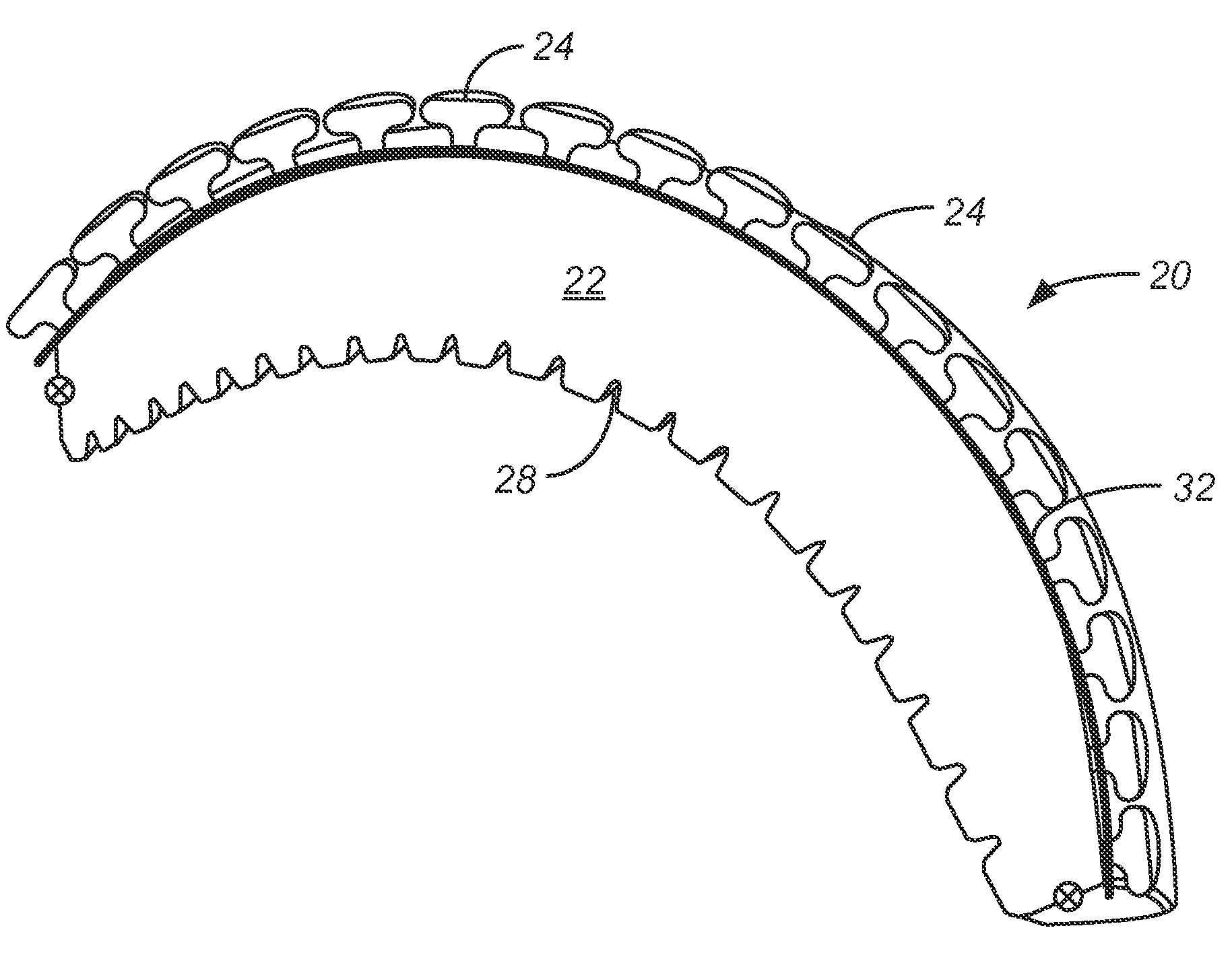
FIGS. “FIGS.4” 4A-4C are three more preferred embodiments for the helmet 20 of this invention. Similar to the helmet in FIGS. The helmets in FIGS. 4A-4C has one or more larger compressive Chambers 22, a harder or yielding shell 30, 32 or 34, larger chamber Vals 26, and grooves 28 to promote circulation. FIGS. The helmets shown in FIGS. 4A-4C are different from the helmet shown at FIGS. 2, 3 by adding multiple smaller compressive chambers 24 to the outside of larger chamber 22, and changing the location or yielding shell 30 and 32.

In FIGS. “In the FIGS. The larger chamber 22, which dissipates most force from a blow, especially the linear force, is preferred. However, the smaller chambers 24, are designed to dissipate rotational forces through a torque sliding motion. The torque sliding motion is very similar to how human skin can dissipate a quick blow. The skin will compress and slide on the bone or muscle to absorb the rotational energy. After that, the muscle will disperse the impact and stop yielding. The smaller chambers should be able to recover their original positions after the rotational force has dissipated. The smaller chambers 24 can contain fluids, such as air, liquids, gels, or other gases. They may also be made as a soft, cushioning unitary piece.
FIGS. 4A-4C show how a hard shell 32, 34 or a yielding shell 30 can be placed in different places relative to the chambers 22-24 of the present invention. FIG. FIG. 4A shows that the hard shell 30, or yielding, is placed outside the larger 22- and smaller 24-chambers. The shell 30 placed on the helmet’s outside corresponds best to the conventional sports helmets. The FIG. 30 shell is more effective in protecting the larger, softer chambers 22 from environmental contamination and damage than the FIG. 4B-4C embodiments are not as effective in cushioning the head against a rotational impact. FIG. FIG. 4B shows the hard shell 32, which is either yielding or hardened, placed between the smaller chambers 24 and 22. This arrangement allows smaller chambers 24 to deform, slide and absorb energy under rotational blows. This allows for the desired soft landing. However, lineal and rotational energy absorption do not occur simultaneously. The disadvantage is that the small compressive rooms 24 are more vulnerable to environmental contamination and damage. However, this can be corrected by wrapping the smaller chambers 24 in a flexible, thin, less friction skin. It may also be more difficult to make the shell 32, which is hard or yielding, between the two chambers 22, 24, especially if the chambers 22, 24- are to be formed together. Alternativly, the shell 32 can be made with slots or holes and placed between the chambers 22, 24, by inserting smaller chambers 24 into the shell 32. FIG. FIG. To make the helmet 20 more comfortable and to ensure proper fit, an extra soft cushioning layer 36 can be placed under the hard shell 34.
FIG. FIG. 5 shows how valves 46 may be placed at each bottom of each mushroom-shaped compressive chamber 44. This is an alternative embodiment of the helmet 40. The smaller chamber valves 46 enable the smaller chambers 44, which are kept at a different pressure than the larger chamber 42, to remain firm and comfortable. A larger chamber valve 48 can be opened to allow fluid to escape, but not the smaller chambers 44.
FIGS. FIGS. 6A-6D show how smaller chambers and structures can be made in different sizes and shapes according to the invention. FIG. FIG. 6A shows a top view of an oval-shaped mushroom-shaped structure 44, as illustrated in FIG. 5. These smaller, oval-shaped chambers 44 can be preferably patterned in columns and offset rows to enhance their ability to dissipate rotational force impacts. FIGS. FIGS. 6B-6C illustrate that smaller chamber heads 52, 54 may also be square or rectangular in shape. Again, they are patterned in offset columns and rows. FIG. FIG. 6C shows how the smaller chamber heads 56 may be diamond-shaped while still being patterned with offset rows or columns.
FIGS. 7A-7B demonstrates how small spring structures 60 can replace smaller mushroom-shaped chambers 24, 44. FIG. FIG. 7A shows an example of a spring structure that consists of a horizontally rotating spring 62 placed between a upper contact surface 61, and a lower surface 64. The spring 62 will contract as shown in FIG. 7B to absorb the force rather than transmit it. FIG. 7B shows a similar structure 70 with a flexible tube 72. 7C. 7C. FIG. 7C shows the tube 72 positioned between a contact surface 71 and surface 74. A flexible polymer can be used to make the tube 72. FIG. FIG. 7D shows that a blow to the tubular structure 70 results in the tube 72 absorption of the force.
FIG. 8. shows how the bicycle helmet 80 according to the present invention might appear with smaller chambers 82 made of diamonds. They can be made to look more athletic by being aesthetically decorated and covered with thin, flexible, frictionless skin. FIG. FIG. 9 illustrates how a football helmet 90 according to the present invention might appear with smaller oval-shaped mushroom-shaped chambers 92 on its exterior. Slots 85 can be made in FIGS. The present invention offers superior protection. To allow for better ventilation, helmets 8 and 9 can be used. Similarly, FIGS. FIGS. 10 and 11 illustrate how protective knee pads 100 or elbow pads 100 might look with smaller mushroom-shaped chambers 102 and 112 on the exterior surfaces. Polymer springs or tubular structures can be used instead of the smaller mushroom-shaped chambers 82 to 92, 102 and 112. Each of these protective structures has a flexible outer structure which serves as a rotational force-dampener. It is best integrated with an inner larger chamber that serves to dampen the linear impact force.
The protective athletic equipment of this invention should be custom-fitted to the body of the athlete in order to increase its effectiveness. This custom fitting is done by creating three-dimensional scans of the protected body parts. Landi’s U.S. Patent Application Publication No. 0056004 describes a method for scanning body parts in order to create three-dimensional scanned pictures. 2011/0056004 is hereby incorporated into reference. A laser scanning system that relies on laser triangulation can be used, as described in the Landi publication. Three-dimensional data can easily be obtained by drawing a triangle between scanner lens, laser, and body part to be scanned. It is possible to determine the distance between the scanner lens, laser, and the angle of the laser provided by a galvanometer. This information can be used to calculate the X,Y,Z coordinates of the body surface being scanned. The galvanometer sweeps the laser across a portion the body part. This rotates a small mirror which reflects the laser. The lens is used to focus the laser on the surface of the body and capture it using a charge-coupled device inside the scanner. Software manipulation can create dense point clouds. The 3D Digital Corp., Sandy Hook, Conn, offers one such model, the ES scan model.
A collection of scans for a portion of the body may be needed to create a 3D image. This process can be done using 3D software such as SLIM 3D Software from 3D-Shape Germany. SLIM software aligns scans based on common features between them and registers them as one global 3D model. Software can automatically align data if there is overlap between two scans. The software will use markers to merge and align the scans if there isn’t enough overlap or common features. To create a clear image, the software smoothes, fills in holes and refines scans. The 3D digital model can be exported to popular 3D formats and edited or manipulated with third-party software such as computer-aided designing (CAD).
Other technologies can also be used to obtain the three-dimensional representation of a body’s parts. A coordinate measuring machine (CMM), for example, can be used. CMMs are used to measure the geometrical properties of objects. A machine can be operated manually by an operator, or via a computer controlled system. A probe is attached to the third moving axis of a machine to measure. The probe can be either mechanical, optical, laser or white light. Brown & Sharp, Mitutoyo and Starrett all have CMMs. Another method is to cast the material around the body and then set it to form a mold once separated. Hand measurements can also provide three-dimensional data.
Protective athletic equipment can be made by blow molding or injection molding once the measurements of the body part are known. Injection molding allows for the production of parts by injecting material in a mold. The material for the part is heated in a barrel and then mixed into a mold cavity. It cools and hardens according to the cavity’s configuration. The manufacturing process that forms hollow parts is called blow molding. There are three types of blow molding available: extrusion blow mold, injection blow mold, and stretch blow mould. The process of blow molding begins with melting the plastic and then forming it into a preform or parison. A parison is a piece of plastic that looks like a tube. It has a hole at one end where compressed air can pass. The parison is then placed in a mold, and compressed air is pumped through it. The pressure of the air pushes the plastic to the right size. After the plastic has cooled and hardened the mold can be opened and the part can be ejected.

Click here to view the patent on Google Patents.