Invented by Daniel H. Forrest, Vinod Dasa, Kenneth Douglas Burnette, W. Brent Pearson, Christopher J. Rich, Albert Hernandez, Sight Medical LLC
Medical devices are used to diagnose, treat, and prevent various medical conditions. They range from simple devices such as bandages and syringes to complex devices such as pacemakers and artificial joints. The selection and implantation of these devices require careful consideration and planning to ensure that they are safe and effective for the patient.
Processing and apparatus for managing the selection and implantation of medical devices refer to the tools and systems used to streamline the process of selecting and implanting medical devices. These tools and systems include software programs, databases, and other technologies that help healthcare professionals make informed decisions about which devices to use and how to implant them.
One of the key drivers of the market for processing and apparatus for managing the selection and implantation of medical devices is the increasing prevalence of chronic diseases such as diabetes and cardiovascular disease. These conditions require the use of medical devices such as insulin pumps and stents, which need to be carefully selected and implanted to ensure their effectiveness.
Another driver of the market is the increasing demand for minimally invasive procedures. Minimally invasive procedures require the use of specialized medical devices that can be implanted with minimal disruption to the patient’s body. These devices need to be carefully selected and implanted to ensure that they are effective and safe for the patient.
The market for processing and apparatus for managing the selection and implantation of medical devices is highly competitive, with many companies offering a wide range of products and services. Some of the key players in the market include Medtronic, Johnson & Johnson, Boston Scientific, and Abbott Laboratories.
In conclusion, the market for processing and apparatus for managing the selection and implantation of medical devices is growing rapidly due to the increasing demand for medical devices and the need for efficient and effective processes to manage their selection and implantation. Healthcare professionals need to carefully consider the tools and systems available to them to ensure that they are making informed decisions about which devices to use and how to implant them. As the market continues to grow, we can expect to see continued innovation and development in this area.

The Sight Medical LLC invention works as follows
A method for selecting the right instrument set for an orthotic implant procedure. This method uses a computer programed with a data structure that stores (i) an array of implant components and instruments, and (ii) the surgical instruments used in performing the procedure. This method determines the type of components to be used in the procedure and then chooses a subset of surgical instruments that are appropriate for each surgical technique. This method arranges sub-sets of surgical instruments and implants instruments in a specific order, based on a determination of the sequence of bone cuts that will be performed during the procedure.

Background for Processing and apparatus for managing the selection and implantation of medical devices
The procedure for implanting artificial joints is often complex and involves many steps such as sizing, alignment, cutting, etc. In order to properly implant an artificial joint (hereinafter ‘implant?), Most implant manufacturers offer a variety of components and tools that can be used to properly insert the artificial joint. The surgeon will need to choose the right size for each patient. Surgeons prefer to have representatives from the implant manufacturer assist with selecting and preparing components and instruments for surgery due to the sheer volume of components and tools involved in implant procedures. The art of implant surgery would benefit greatly from a system that standardizes, streamlines, and organizes the types and types and components which are required to be transported into the operating room. This system could also help reduce the chance of an incorrect instrument being used (e.g., incorrect cutting guide, sizing test, etc.). used during surgery. Additionally, it would be a significant improvement to provide a system which assists surgeons and other healthcare personnel to more efficiently use patient data in selecting implant sizes and types, tracking and maintaining an efficient inventory of implant components/instruments, and assisting surgery personnel in the efficient deployment of implant components/instruments during surgical procedures.
One embodiment of this invention is a method for selecting an instrument set to perform an orthopedic implant procedure on a patient. This method uses a computer that is programmed with a data format to store: (i) an array of implant components and instruments; (ii) the surgical instruments used in performing the procedure. This method determines the type of components to be used in the procedure and then chooses the appropriate surgical instruments according to that determination. This method arranges sub-sets of surgical instruments and implants instruments in a specific order, based on a determination of the sequence of bone cuts that will be performed during the procedure.
Another embodiment is a method for managing implants. The method includes (i) an implant storage area, (ii), a storage sensor located near the storage space, which is configured to detect implant parts, and (iii). a system computer communicating directly with the storage sensor. The method determines which implant components are due to be removed from the storage area, then operates the storage sensor to notify the computer system that the implant components have been removed.
Another embodiment of the invention is an Implant Management System that includes an implant storage area and a storage sensors located proximate to the storage space. The storage sensor is designed to detect implant components. The management system includes a deployment sensor that detects implant components, and a computer system communicating with the storage sensor. Software will be installed on the system computer to perform the following steps: (i) receiving data that represents a set implant components that are scheduled to leave the implant storage space; and (iii). receiving data that indicates that the storage sensor detected the set; and (iii). receiving data that indicates that the deployment sensor has detected these implant components at a designated destination.
A computer system can be used to predict the size of an implant component. This is another embodiment of the invention. This method creates a medical image of anatomical parts on a computer selectable coordinate scheme using a user interface. This method allows users to select multiple points from the coordinate system that correspond to specific anatomical features. Then, the algorithm determines the anatomical distance between the minimum of two points. The method then compares the anatomical separation to a database that cross-references certain anatomical differences with the corresponding size for the implant component.
Another embodiment is a method for selecting an instrument set to perform an orthopedic implant procedure on a patient. This method creates a computer system that is programmed with a data format to store: i. an array of implant components and instruments; and, ii. A set of instruments used in the operation. The method uses a computer user interface to calculate the implant component size for each patient. It then generates a subset of implant components and instruments, based at most in part on the estimated implant component size for each patient. The method creates a visual listing of the subset of implant instrument in a specified order and then physically arranges them substantially in that order to prepare for the implant procedure.
The above is a summary of a few embodiments. The invention also includes many other embodiments. Some are described in the detailed description below, others not.
One embodiment of this invention provides a method for selecting an instrument set to perform an orthopedic implant procedure on a patient. The implant device can be used for any joint, including the hip, knee, elbow, and shoulder. However, it could also be used for other bone implants, such as pacemakers or stents or soft tissue repair of the knee and shoulder (e.g. implant components and instrumentation used for ACL and rotator-cuff repair). ?Implant procedure? Any medical procedure that involves the placement, adjustment, correction, or addition of an implant component in a person’s (or another animal’s) body. These methods and apparatuses can be applied to both existing and future-generation implants and procedures. Although many of the illustrations are focused on a total knee implant and total knee arthroplasty procedure, it could also be applied to other parts of the body. Some of the described embodiments allow you to select a subset?surgical instruments. as well as?implant instruments. which are related to?implant parts? All of these are described below. Other embodiments are used to aid in inventory control of implant components and to assist personnel in the deployment or implantation.
An ‘implant component’ is defined herein. An implant component is a thing, such as a prosthetic device, tissue or other object, that has been surgically implanted into a person’s body. It can be temporary or permanent. One example of implant components in total knee arthroplasty is a femoral, tibial, and patellar component. There are many sizes and configurations for these components. The femoral implant components may have?cruciate retention? or ?posterior stabilized,? The tibial baseplate can be?modular? Or?nonmodular? The patella component can be?onset? Or?inset? Modular tibial components are composed of a tibial insert and a tibial plate. A non-modular component is one, unattached piece. Many components of implant can vary depending on bearing design, materials and bone-implant fixation methods, such as whether or not the components are cemented or affixed with cement. A complete list of the various components for a particular implant system can be found in Tables A1.1 through A1.23 in Appendix A. This is also available in the U.S. provisional patent Ser. No. No. All references herein to tables marked with the letter “A”? (e.g., A1.1, A1.2, A2.1, etc.) Refer to the Appendix in U.S. Ser. No. 62/098,877.
An ?implant instrument? An implant instrument is a device that conforms to the type of implant being inserted. It is usually supplied by the implant manufacturer as an accessory to the components. Implant instruments are used to create or facilitate the proper anatomy for the implant components. There will be associated instruments for the femoral, tibial (baseplate and insert), or patellar components. One example of implant instruments in total knee arthroplasty is femoral trials and tibial baseplate trials. Tibial insert trial trials. Patellar drilling guides. Implant instruments can include any instrument that is used for component sizing, bone shaping or component preparation. The tables A2.1 through A2.18 provide a more detailed listing of the implant instruments that are used in a conventional Total Knee System.

A ?surgical instrument? A device used by a surgeon to organise and effect the surgical outcome, especially in relation to implants. However, it is not usually considered an instrument for implant surgery. These surgical instruments can include, but not be limited to, bone cutting and alignment tools. One example of bone-cutting instruments for total knee arthroplasty is cutting guides, alignment and resection guides. These instruments are used for alignment, cutting, measuring and configuring joint extremity alignment, balance, measurement, and configuring. You can find a more detailed list of surgical instruments that are compatible with conventional implant systems in Tables A3.1 through A3.15.
Many of the figures in the present application show methods and systems as flow charts. The methods can be implemented using software that runs on a general-purpose computer, which may include a CPU, user interface and the necessary memory components. A general purpose computer could also include handheld computers like smart phones, especially when the user interfaces with other devices within the overall system.
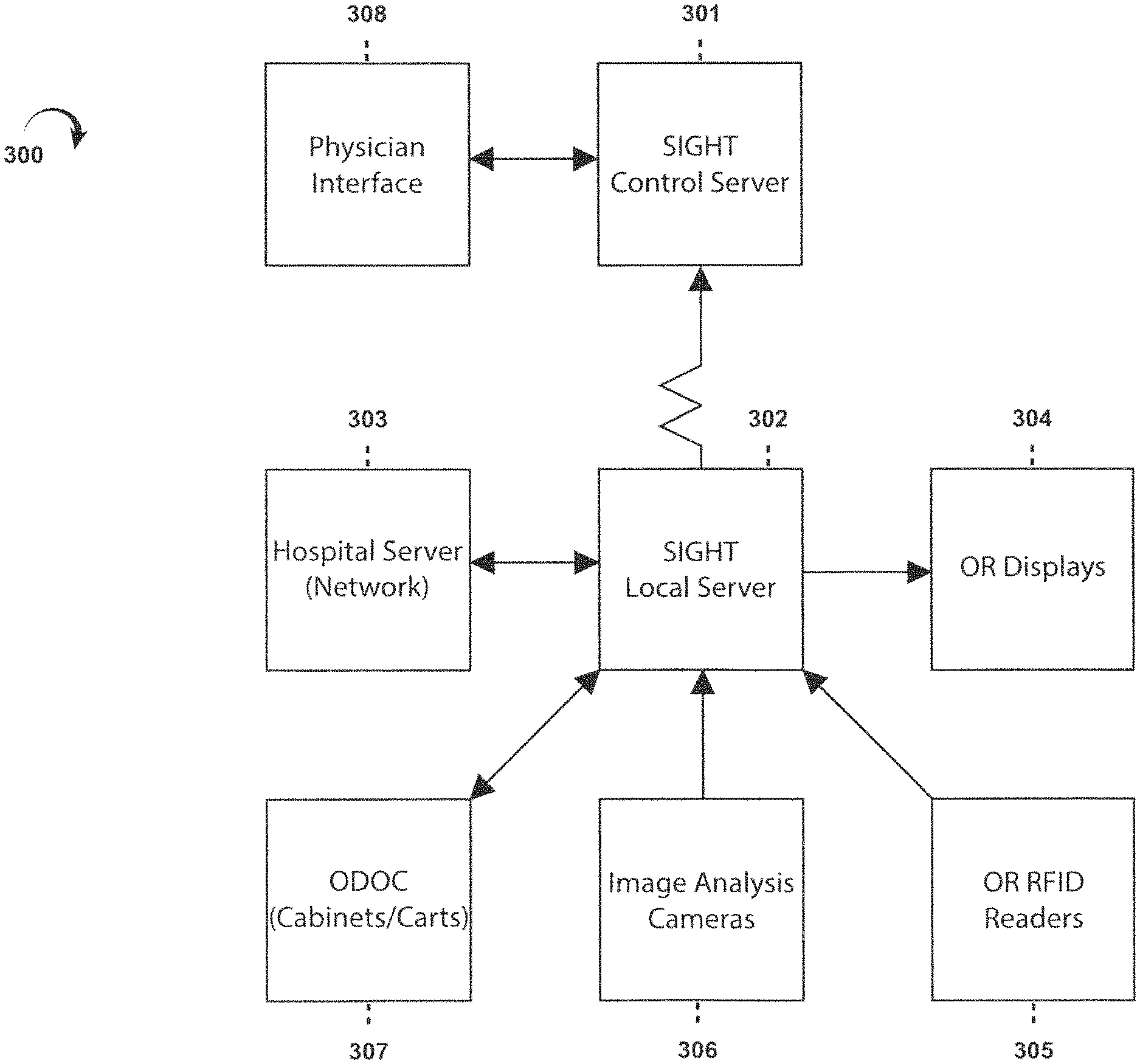
FIG. “FIG. 17” is a block diagram that shows various components of an embodiment of the 300-member overall system for the execution of the various methods in this application. Sometimes, the general system 300 may be referred herein by the trademark “SIGHT?”, e.g. the SIGHT system. This embodiment has a central server 301 that is typically located far from other elements. FIG. 17 shows most of the elements. 17 can be found at a hospital, or any other medical facility that will perform the implant surgery. Thus, FIG. FIG. 17 shows the hospital network 303 with a local? SIGHT server 302 is located in the hospital, and in communication with central SIGHT server301. This can be done for example via the hospital network. FIG. FIG. 17. shows only one set of elements that would typically be found at a hospital. However, it is clear that the SIGHT central servers 301 would be communicating to many hospitals networks 303 across the country or worldwide. Each hospital would have a SIGHT local server 302. This application refers to a “computer” This application may refer to a?computer? These terms could include, for example, central server301, local server 302, and the two servers that act together as one computer system.
Other system components typically found in every hospital include one or two computer-enabled cabinets 307 to hold and assist in the management and operation of implant components and instruments. The cabinets can be identified by the trademark ODOC? (e.g., ODOC cabinets). These are described in more detail below. The ODOC cabinet 307 houses the SIGHT localserver 302 in many embodiments. Many other elements can communicate with the SIGHT server 302. Other elements include bar code scanners, RFID tag readers 305 and computer displays 304 that are located in the ODOC cabinet. Image analysis camera(s), 306 could also be part of the overall system, in addition to RFID readers or bar code scanners. Wherever the term “server” is used in an application, it means any general purpose or special purpose computer that can perform the functions described herein. When the term “server” is used in an application, it means in the broadest possible sense any general-purpose or special purpose computer that can perform the functions herein.
Normally, each participating physician in the SIGHT program will have a physician Interface 308 that allows them to send and receive information. One example of a physician interface is a smart phone or tablet that runs an app to establish communication with the SIGHT central servers 301 and the local server 302 through the hospital network.
FIG. 17 shows some examples of the functionality of SIGHT system. 17 can be viewed starting with FIG. 1. FIG. FIG. 1 shows a high-level flowchart that illustrates a series of steps in one process to obtain implant sizing data and select a narrowed list of implant components and instruments most likely for the procedure being considered. FIG. 3 shows the third step. FIG. 1 shows how the process starts with identifying key anatomical areas related to the bone joint, or other body part that will be replaced or corrected by the implant. The flow chart in FIG. shows this step in greater detail. 2. Step 14: A medical image from a radiological monitor, or any other type of monitor, is superimposed or overlayed on a computer selectable Coordinat System. This may be a system that forms a grid using individual pixels or groups. It allows a user to choose?points? You can use a touch screen technology or a mouse to control the cursor to move around the image (image coordinates). As used in this document, “medical image” means: Any technique that can be used to image body parts (either conventionally or in the future), including x-rays, MRIs and CT scans. FIG. FIG. 3 shows conceptually an xray of human legs, overlayed on the computer grid 24, Step 22 in FIG. 2. The user is asked whether they want to use a user-guided procedure to identify key anatomical characteristics or if the software will perform an image recognition algorithm to identify these anatomical elements. Step 15 in the user-guided procedure is shown in FIG. 2. The user is prompted to enter the scale for the medical image. FIG. FIG. 3 shows the 35 scaling marker, which allows the computer grid to be correlated and scaled with the medical images. Step 16 is where the user uses the scaling marker to scale the medical image to the computer Grid Scale. This is similar to how conventional image viewing software works. As shown in FIG. 17 and FIG. 18, the scaling marker is used to scale the medical image to the computer grid scale. The method also includes the display of anatomical points on the monitor next to the medical image. FIG. FIG. 3 illustrates images that show the locations of the center and tip of the greater trochanter (image 30), the center and lower trochanter (image 31), as well as the center and lower femoral notchs (image 32), 33, 33, 34, and 35. These images can be used as guides. Click on the anatomical point in the medical image that corresponds to the marker showing the tip of a greater trochanter 25, 26 femoral head, 27 femoralnotch 27, 27 proximal tibia 28 and 29 femoral. FIG. FIG. 2’s steps 18-20 can be used to identify these points using a feature recognition algorithm, such as the one found in The Mathworks Inc.?s computer vision toolbox. No matter which method is used to identify anatomical features and points of interest in an anatomical model, the final step (21) of the method will require the user (e.g. the surgeon who is ultimately responsible for the procedure) to validate that the anatomical points chosen are correct and the measurements resulting from them. The above example shows an image that has been scaled, but there are other medical image formats that don’t necessarily need scaling. For instance, images that conform to the Digital Imagining and Communications in Medicine format (DICOM).
One anatomical characteristic that may be deduced from the identified points is the degree or valgus of deformity suffered in the knee, which is the subject matter of the medical image (step 5, FIG. 1). FIG. FIG. 4 shows one way the system can determine the degree of varus and valgus. The?femoral mechanical angle is the first line. (?FMA?) The line that runs from the center of a femoral head to the center of femoral neck (CFN) is the FMA. The?tibial mechanical angle is a second line. (?TMA?) The line drawn between the centerline of the proximal and middle of the ankle (CA) is called the “TMA?” The computer system can easily determine the relative angle between FMA or TMA because they are made on an electronically rendered grid system.
Returning back to FIG. 1. Step 6, determine the femoral size. FIGS. 5 to 7 illustrate different methods of determining this parameter. FIGS. 5 through 7. FIG. FIG. Both methods require registration of key points of interest for femurs, such as using the electronic grid system in FIG. 3. An anterior-posterior (??AP?) measurement is used in the 43rd step. To determine the femur’s size, distance is used. FIG. FIG. 6A shows an AP view at the distal end 50 of the femur. The user will then register two points in Step 45: the anterior femoral level 51 and 52. In step 47 of FIG. The system then calculates the size of the femoral part. The distance between points 51 to 52 (shown at FIG. 6A is the distance BC along an anterior-posterior line. It is multiplied by the thickness of the anterior Flange 55 (FIG. 6B) of the femoral component 54. This distance AC is shown in FIG. 6B can then be used to determine the closest?AP distance. FIG. 6C. If AC was 59mm in distance, the system would use the FIG. 6C, the system would calculate a size 3 component of the femoral artery.
An alternative method can be found in step 44 of FIG. 5. The points in FIG. 7A are used for this step. 7A are utilized. These are the medial and lateral posterior condyle borders 58, 59. They are usually recognizable in a medial/lateral image of the distal end of the femur (as indicated by the dashed lines in FIG. 7A). 45 of FIG. 5: The user registers the medial and lateral posterior condyle borders 58 and 59. This distance is measured by the system (illustrated in FIG. 7B, also known as the medial-lateral (or?ML) distance. Distance from the distal end of the femoral artery. FIG. 47 is step 47. 5. The system uses the DE determined distance to determine the nearest?ML distance. FIG. 7C. 7C. If ML was 65 mm, the FIG. 7C, the system would calculate a size 3 component of the femoral artery.
FIG. 1. Step 7 determines the size of the tibial portion. FIGS. 8 to 11 show this selection process in greater detail. FIGS. 8 through 11. FIG. FIG. 8 shows how the user can choose from two different methods to estimate the size of the tibial plate. First, you can determine the AP measurement directly of your tibial plateau. This is best explained by reference to FIG. 9A. FIG. FIG. 9A shows the user choosing (step 62a of FIG. 8) The posterior border 71 and the anterior medial borders 72 of the Tibial Plate. In step 63a, the system determines the distance between these points. The measured ‘AP? The distance between points 71-72 is then correlated to the?AP? Distance on the tibial plate, as described in step 64 of FIG. 8 and FIG. 10. To estimate the base plate size, find the nearest standard AP distance for the various base plate sizes (as shown in FIG. 10) corresponds to the measured AP Distance between points 71-72. Non-limiting example: If the measured AP distance between points 71 & 72 was 46 mm, then the base plate size 3 with the standard AP separation of 47 mm would be used to estimate the base plate size. FIG. FIG. 9B shows how the AP distance at the tibial plate can be measured using an axial view, e.g. an axial view created from a MRI, or another similar technique. The user can also select anatomical points that correspond with the posterior border 71.1 and the anterior medial boundary 72 of the tibial plateau.

Click here to view the patent on Google Patents.