Invented by Roger P. Jackson, James L. Surber
The market for medical implant receivers with dual lead in closure mating threads is growing rapidly, driven by the increasing demand for advanced medical implants that offer better outcomes for patients. These implant receivers are used in a variety of medical procedures, including joint replacement surgeries, dental implants, and spinal surgeries.
One of the key advantages of implant receivers with dual lead in closure mating threads is their ability to provide a strong and stable connection between the implant and the patient’s body. This is achieved through the use of two mating threads that are designed to interlock securely, ensuring that the implant remains in place and functions effectively.
Another advantage of these implant receivers is their versatility. They can be used in a wide range of medical procedures, making them a popular choice among healthcare professionals. In addition, they are available in a variety of sizes and configurations, allowing healthcare providers to choose the best option for their patients’ needs.
The market for medical implant receivers with dual lead in closure mating threads is expected to continue growing in the coming years, driven by the increasing demand for advanced medical implants that offer better outcomes for patients. As technology continues to advance, we can expect to see even more innovative and effective implant receivers being developed, further expanding the range of options available to healthcare providers and their patients.
In conclusion, the market for medical implant receivers with dual lead in closure mating threads is a rapidly growing and highly competitive industry. These implant receivers offer a range of benefits, including a strong and stable connection between the implant and the patient’s body, versatility, and a wide range of sizes and configurations. As the demand for advanced medical implants continues to grow, we can expect to see even more innovative and effective implant receivers being developed, further improving the outcomes for patients undergoing medical procedures.

The Roger P. Jackson, James L. Surber invention works as follows
An open implant closure structure consists of a helically wounded guide and advancement structure with at least two helically injured forms thereon. This provides a multi-start closing mechanism that can be used between the spaced arms of an open medical implant cooperating with a mating helically wounded structure. Interlocking flange forms include v-threads. Square threads. Reverse angle threads. Buttress threads. Receivers with break-off extensions.

Background for Medical implant receivers with dual lead in closure mating threads
The present invention relates to a structure for joining parts of a medical implants, in particular closure mechanisms for spinal bone anchors. Some embodiments of this invention can also be used with polyaxial screws.
Bone anchors such as bone screws or hooks can be used in various types of spinal surgery to attach different implants to the vertebrae of the spinal column to stabilize and/or adjust the alignment of the spine. The most common method of providing vertebral support is to place bone screws in certain bones. These bone screws then support or support the rod. Open-ended and closed-ended bone anchors can be used. However, open-ended anchors work best for connecting to longitudinal connecting members like hard, soft, or deformable rods. The anchors are generally inserted into bone either as an integral unit or pre-assembled unit. These units can be in the form of a hook or shank and a connected pivotal receiver. Sometimes, a part of such a pre-assembled unit, such the shank of a polyaxial screw assembly for bone, can be inserted into bone by itself. The receiver portion may then be push-or pop-on assembled.
A typical open-ended bone screw is a threaded shank that has a receiver or head with two parallel branches or arms. This forms a yoke and a slot or channel for receiving a rod or any other longitudinal connecting member. Similar open ends may be found in hooks and other connectors used in spinal fixation techniques. These can also receive rods or other parts of fixation and stabilization structures. After the rod or other longitudinally connecting member is placed into the channel, the open-ended head of such implants usually includes a pair spaced arms that form a channel. There are many types of closures, including slide-on and twist-on. These can be rotated 90 degrees to lock in the position. To prevent receiver arms from splaying, threaded plugs can be used with outer threaded nuts.
As mentioned above, it is quite difficult to press a closure mechanism onto a rod or connector between the arms of an open implant. Although a receiver or head portion of an open polyaxial bones anchor can be angled in order to allow the arms to receive a rod, or any other connector, it is difficult to place the rod between the arms of an implant. A closure structure must also be mated with the implant and used to push the rod, or any other connector downwardly into it. If the closure is a cylindrical, single-start helically wound guide or advancement structure, it must be aligned with one of the implant arm’s mating structures. Then rotate the structure until a portion is captured by the mating guide and advancement structures on both arms. All the while, the closure is being pulled back from the implant while other forces push and pull the rod down. It is more difficult to maneuver mono-axial or integral open implants. The surgeon applies extraordinary force to the implant and closure plug, pulling up on the bone or pushing down on it to position the rod between the implant arms.
A closure structure, top, or plug of invention for inserting between spaced arms on an open medical implant has one or more helically wounded guide and advancement features. Each feature is located at or near the bottom surface of the plug. Each start structure engages and is captured by the respective spaced arms upon initial rotation of closure structure relative to open implant arms. A double-start closure is disclosed according to one aspect of the invention. Each form has a start structure that simultaneously engages a mating form on an open implant arm. The closure plug advances axially toward the rod when the double- or duel-start plug is rotated three hundred sixty degrees between the implant arms. The multi-start closure’s helically wound forms spiral around a cylindrical plug head to receive the complete closure plug between the implant arms. To receive the plug between the implant arms, the illustrated closure must be able to rotate at least once (three hundred sixty degrees). Multi-start closures may be made with two or more coarse helical forms. This can lead to plugs that are less or more symmetrical about the plug body than if they rotate fully between the implant arms.
An illustrated multistart closure and mating open implants is in the form non-threaded interlocking flange forms. Multi-start closures with other geometries are also disclosed, including helically wounded threads like square, reverse angle, buttress and square. For minimally invasive surgery, the multi-start closure can be cannulated.
Another illustration of multi-start closure is shown. It shows a bone screw assembly with an open receiver and a pair of opposing arms. Each arm has a guide and advancement structure that allows simultaneous mating engagement with the multi-start helically wound closure. An open bone anchor receiver with integral upwardly extending break off tabs is another embodiment of the invention. This also has the guide and advancement structure to mating with multi-start closure. A further embodiment includes an attachable/detachable guide tool cooperating with such a multi-start open receiver, the tool having inner guide and advancement structures located near a bottom thereof for rotatably and matingly receiving the multi-start closure and being synchronized with the receiver guide and advancement structure for rotating and driving the multi-start closure downward from the guide tool to the receiver.
Objects of this invention also include apparatus and methods that can be used easily and are specifically adapted to the intended use. The tools are relatively inexpensive to make. The following description, along with the accompanying drawings, will reveal other advantages and objects of the invention.
The drawings are a part this specification. They illustrate various objects and features of the invention and show exemplary embodiments thereof.
As necessary, detailed embodiments for the present invention have been disclosed. However, it should be understood that these embodiments are only exemplary of the invention and may contain other forms. Specific structural and functional details are not intended to be limited. They serve as a basis for claims and to teach one skilled in the art how to use the invention in almost any structure. Also, it should be noted that the reference to top, bottom and up and down in this application refers only to the arrangement shown in the various illustrations. It does not restrict the actual positioning of bone attachment structures.

Further, pitch, lead and start are terms used to describe helically wounded guide and advancement structures. Lead is the distance along the axis a closure plug is covered by one complete turn (360 degrees) of the closure connector with respect to an open implant. Pitch refers to the distance between a crest or outer point of a guide or advancement structure from the next. In a single-start thread form, like a single-start, helically wound, v-thread closure, pitch and lead are the same. A single start is one ridge, or helically wound, that is wrapped around a cylindrical center, or in this case, around a cylindrical closure body. This means there is only one surface or base at the forward end of the closure body, which initially contacts a mating structure on an open implant. A single-start closure is rotated 360 degrees. The closure advances axially by one ridge or one form. Double-start refers to the presence of two ridges, forms or other structures wrapped around a core and therefore there are two surfaces or structures on the closure plug. A double-start body will rotate 360 degrees once it has reached the end of its rotation. This means that it has advanced axially by two ridges or forms. Multi-start refers to at least two, but may have up to three of these ridges or forms around the core body.
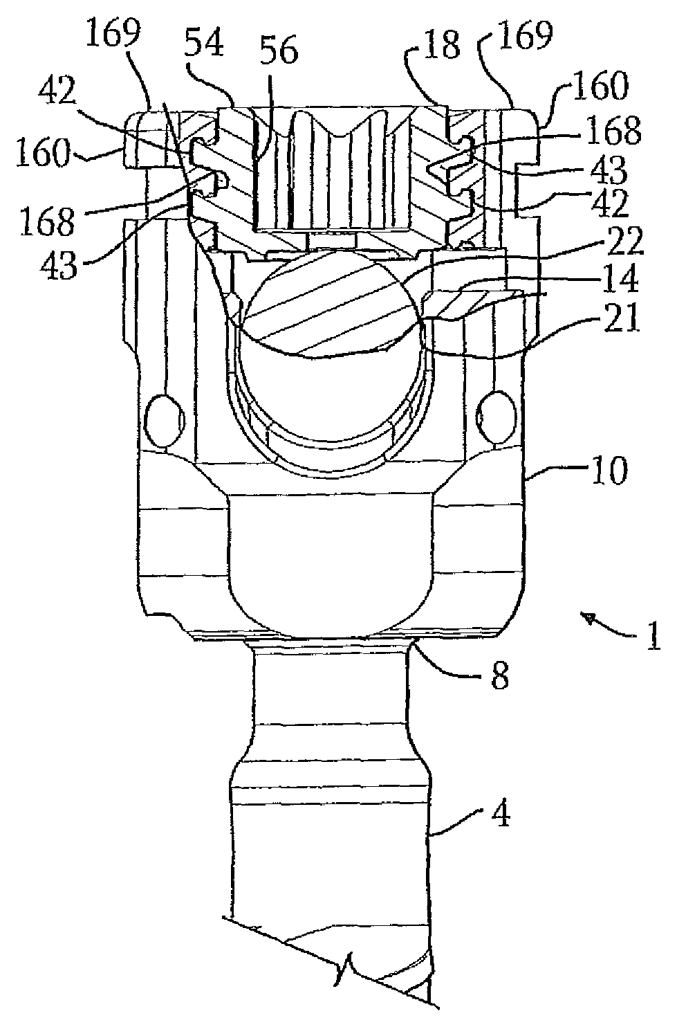
With reference to FIGS. FIGS. 1-8 and especially FIG. 8 The reference number 1 represents an open implant, in the form of a multiaxial bone screw assembly or apparatus that works with the illustrated closure structure 18. U.S. Provisional Patent Application No. Provisional Patent Application No. 61/631/746, filed Jan. 10, 2012. It is incorporated herein by reference (hereafter the “746 application”) and will therefore not be described in detail. FIG. 746 describes the details of each component in greater detail. 8. Multi-start closures, such as the 18-year-old closure, can be used with many open implants, including but not limited to polyaxial screws, monoaxial or fixed screws and hooks. These open implants require a plug or closure mechanism in order to attach a rod, other implant member, or rod, to a vertebrae or other bone. The assembly 1 is just one example of multi-start closures that may be used with the invention.
Briefly, the illustrated assembly 1 comprises a shank with an upwardly extended upper portion or capture mechanism 8; an open receiver 10, a retaining or retainer (not seen), a compression insert 14 and a multi-start closure or plug 18. The plug 18 is a cylindrical plug with a double-start Helically wound Flange-form. The closure 18 engages and captures a longitudinal connector member, such as a rod 21, which presses against the upper shank portion 8 and is attached to the retainer 10. This in turn presses against the receiver’s inner surface 10 to capture and fix the longitudinal connect member 21 and fix it relative to a vertebra (not illustrated). The shank 4, illustrated receiver 10, and the shank 4, can cooperate so that the receiver 10, and shank 4, can be secured at any one of a variety of angles, alignments, or rotational positions relative to one other and within a select range of angles from both sides to rear. This allows for flexible or articulated engagement between the receiver 10 & shank 4.
The illustrated rod 21 is cylindrical and non-elastic, with an outer cylindrical surface 22. In other embodiments, however, the rod 21 can be elastic, flexible, and/or have a different cross sectional geometry. The rod 21 can be made from various metals, alloys, and deformable plastics. This includes rods made of polyetherketone (PEEK), polycarbonate (PCU), and polyethylenes. The assembly 1 can also be used with longitudinal connecting members that are of different shapes and/or include a tensioned cable, as described in detail in the 746 application.
It should be noted that receiver 10 contains guide and advancement structures168, which are shown as interlocking forms of flange forms. This is described in more detail in the U.S. Patent. No. No. 6,726,689 is also included by reference herein. Alternately the receiver cooperating forms (e.g. 168) must be of a different helical shape. These receiver cooperating forms (e.g. 168) can also be thread-like or not-thread-like discontinuous advancement structure receiving shapes for operating under rotation and moving a multi-start closure mechanism downward between the receiver arms 160.
With special reference to FIGS. “With particular reference to FIGS. The form 42 has a start structure or surface 46 while the form 43 has a start structure or surface 47. Each form 43 and 42 may be helically wound in a variety different forms, including those described by Applicant’s U.S. Patent. No. No. 6,726,689 is incorporated herein. It should be noted, and also discussed in greater detail later herein, that each of these closure structure guide or advancement structures forms 42 and 43 could alternatively take the form of a buttress, a square, or a reverse angle thread. These are for operably guiding the closure between the arms 10 and moving it downward. Preferably, they must have such a nature to resist splaying the receiver arms as the closure 18 is advanced into receiver channel. FIGS. 42 and 43 show the specific flange forms 42, 43. Applicant’s U.S. Patent. 1-7 provides detailed information on the flange forms 42 and 43 illustrated in FIGS. No. No. 6,726,689 is incorporated herein by reference. These interlocking forms of flange are preferable because they provide additional strength and counter any reductions in strength due to the reduced profile receiver 10. This may be more advantageously engaged longitudinal connecting member components.
The illustrated closure structure 18 includes a top surface 54 that houses an internal drive 56. This aperture is shown as a star-shaped internal driver such as the one sold under trademark TORX. It may also be a hex drive or any other internal drives such a slotted, tri-wing or spanner drive or two or more apertures with different shapes. The driving tool (not illustrated) is sized and shaped to engage with the internal drive 56. It can be used for rotatable engagement or, if necessary, disengagement of closure 18 from receiver 10 at arms 160. The bottom or base surface 58 of the closure has a rim 60 that allows engagement and penetration into certain embodiments of this invention’s rod 21. The closure top 18 also includes a cannulation through bore 62, which runs along the central axis and through the drive base surface 63, and bottom surface 58. This through bore allows for the passage of a length (not shown) of wire through the closure 18, interior to guide the insertion of the closure’s top into the receiver arms 160.
The closure structure 18 is a helically wound form start structures 46, 47 and 43 respectively. They are located on opposite sides to the closure plug body 40. They are both adjacent to the bottom surface 58. FIG. FIG. 3 shows that, for example, the closure 18 is rotated into receiver 10 between receiver arm 160. The receiver has a guide or advancement structure 168, and each of the receiver arms 160 has a guide or advancement structure 160. When the start 46 engages mating structure and advancement structure 160 on one arm 160, and the start 47 simultaneously engages guide/advance structure 168 in the opposing arm 160. Both forms 42 and 43 are simultaneously captured by the mating form 168 on both arms 160. The structure 18 rotates axially between the arms 160, pressing down evenly upon the captured rod 21. The closure plug 18, illustrated as a duel-or double-start closure, 18 rotates one turn or pass (3 hundred sixty degrees) between implant arms 160. It then presses down evenly upon the captured rod 21. The closure 18 illustrated is sized to allow at least one complete rotation of the plug 18 (three hundred sixty degrees) with respect to the receiver 10, open arms 160, which will substantially receive the plug between its implant arms. Each of the start structure 46 and 47 has a leading surface with at least one curvate. At least one curvate area must have at least one radius curvature. One embodiment has at least one curvate area that is both concave or convex. Multi-start closures may include two or more coarse helical forms. This results in smaller or larger forms per axial distance spiralling around the closure plug body. Plugs that rotate more than one complete turn between the implant arms will not be fully received by the plugs. The preferred helically wound forms for the multi-start closures of the invention are designed so that they spiral around a cylindrical plug-body to the extent that the closure rotates at minimum ninety-one degrees to receive the closure plug between its arms. Preferably, the guide and advancement structures should be sized to allow for at least one turn (three-hundred sixty degrees) of the closure between 10 receiver arms. It can also allow for up to two to three rotations between implant arms to fully receive the closure.
The receiver 10, retainer 12, and 14-piece compression insert are used together with the shank 4. This assembly is attached to the rod 21 (or other longitudinal connecting member) as described in the ‘746 patent incorporated herein. The shank 4, other parts of the bone screw assembly, the rod 21 (also with a central lumen, in some embodiments), and the closure top 18 with the central bore 62 may be inserted percutaneously or minimally invasively using guide wires. The rod 21 or another longitudinal connecting member can be positioned in an open, percutaneous or combined with at least two bone screws assemblies 1 (or any other open implants). Next, the closure structure 18 must be inserted into the receiver and advanced between each arm 160. Rotating the closure structure 18 with a tool engaging with the inner drive 56 is necessary to reach a desired pressure. At that point, the rod 21 engages the U-shaped seating area of the compression insert 14. The insert is further pressed against the shank upper section 8 and attached retainer until it locks frictionally with the receiver 10. Before locking the insert 14 against shank head 8 the shank can be plied to any desired position relative to receiver 10. Then, the polyaxial mechanism is locked by mating the multi-start closure 18 with receiver 10. The ‘746 patent incorporated herein shows different angular and articulated positions for the shank 4 in relation to the receiver 10.
With particular reference to FIGS. 3. and 8. As the multi-start closure 18 rotates and moves downwardly in the respective receiver 10, rim 60 engages with and penetrates rod surface 22. The closure 18 presses downwardly against the rod 21 and biases it into compressive engagement. This forces the shank upper section 8 and attached retainer into locking relationship with the receiver. The retainer outer frictionally abuts an inner spherical sitting surface of the receiver 10. The closure top can be used to fix the bone screw shank 6 to the receiver by applying torque of 80 to 120 inches. For example, if the shank 4 is placed at an angle relative to the receiver 10, then a portion of shank 8 may be in frictional contact with a portion the receiver’s spherical seating surface.

If the rod 21 is to be removed from one of the bone screw assemblies 1, or if the rod 21 is to be released at a specific location, the driving tool (not illustrated) can be used to disassemble the rod 21. It mates with the 56-volt internal drive on the closure structure 18. This allows you to rotate the closure structure and take it from the cooperating receiver 10. The disassembly process is reversed to that described in the previous section for assembly.

Click here to view the patent on Google Patents.