Invented by Jordi Parramon, Boston Scientific Neuromodulation Corp
The market for external powering of implantable medical devices that are dependent on the energy from provided therapy is growing rapidly. This market includes a range of devices that are designed to provide power to implantable medical devices, including external battery packs, wireless charging systems, and energy harvesting technologies.
One of the most popular options for powering implantable medical devices is external battery packs. These devices are designed to be worn outside the body and can be connected to the implantable device via a cable. External battery packs are typically rechargeable and can provide power to the implantable device for several days or even weeks.
Another option for powering implantable medical devices is wireless charging systems. These systems use electromagnetic fields to transfer power wirelessly from an external charging pad to the implantable device. Wireless charging systems are particularly useful for devices that are implanted in hard-to-reach areas of the body, such as the brain or spinal cord.
Energy harvesting technologies are also being developed to power implantable medical devices. These technologies use the body’s own energy to generate power for the implantable device. For example, some energy harvesting technologies use the movement of the body to generate electricity, while others use the body’s own heat or light to generate power.
The market for external powering of implantable medical devices is expected to continue to grow in the coming years. As more and more patients opt for implantable medical devices, the demand for reliable and safe power sources will only increase. In addition, advances in technology are likely to lead to the development of new and more innovative ways to power these devices.
In conclusion, the market for external powering of implantable medical devices that are dependent on the energy from provided therapy is a rapidly growing industry. With the development of new technologies and the increasing demand for implantable medical devices, this market is likely to continue to expand in the coming years. As a result, patients can expect to have access to a range of safe and reliable power sources for their implantable medical devices.

The Boston Scientific Neuromodulation Corp invention works as follows
An implantable medical devices system comprises an implantable medical instrument for stimulating therapy and two external power sources. When the stimulation therapy is low-energy therapy, the first external power source powers the implantable medical devices. The first external power source may be used to recharge the battery of the implantable medical devices. When high-energy stimulation is used, the second external power device can be used to power the implantable device. A disposable patch may be used to attach power to the implantable medical devices. An implantable medical device could communicate data to this power device in order to adjust the strength of the charging fields it generates.

Background for External powering an implantable medical device that is dependent on the energy from provided therapy
Implantable stimulation device generate and deliver electrical stimuli nerves and tissues to treat various biological disorders. These include pacemakers to treat cardiac arrhythmia and defibrillators for treating cardiac fibrillation. Retinal stimulators are used to treat blindness. Muscle stimulators can produce coordinated limb movement. Spinal cord stimulators can be used to treat chronic pain. Cortical and deep brain stimulators are used to treat motor and psychological disorders. Occipital nerve stimulators can be used to treat migraine headaches. Although the present invention could be applicable to all of these applications, the following description will focus on its use in a microstimulator system according to U.S. Patent Publ. No. No. 2010/0268309 is incorporated by reference in its entirety. Although the invention is described in the context a microstimulator system, it can be used in any implantable stimulation device system such as a Spinal Cord Stimulator, which treats lower back pain. No. No. 7,444,181, is included herein by reference in its entirety. ?Microstimulator? The following should be taken to mean any implantable stimulator.
Microstimulator devices typically comprise a small, generally-cylindrical housing which carries electrodes for producing a desired stimulation current. These devices are placed proximate the target tissue in order to permit stimulation current to reach the target tissue. This allows for therapy for many conditions and disorders. Microstimulators usually include or carry stimulating electrodes that are intended to contact patient’s tissues. However, they may also have electrodes attached to the device’s body via a lead. Microstimulators typically have two electrodes. However, microstimulators may also include more than one electrode in an array as disclosed in U.S. Pat. No. No. 7,881,803, is included herein by reference in its entirety. The simplicity of microstimulators is a benefit. The microstimulator’s small size allows for easy implanting at any site that requires patient therapy.
FIG. “FIG. The microstimulator 10, as shown, includes a power source 14, control circuitry (e.g. a microcontroller), 16, and various electrical circuitry 20, including stimulation circuitry to form stimulation pulses at electrodes 12a/b and coil 22. A stimulation program (SP), which is stored in memory, can be used to define stimulation pulses. This memory can be associated with either the microcontroller 16 or the electrical circuitry 20, as well as both the microcontroller 16 or both. As explained below, a stimulation program can define the frequency, amplitude, pulse width and frequency of pulses or other parameters.
Electrical components can be integrated by a circuitboard 24 and housed in a capsule 26. This is usually a thin, elongated cylindrical cylinder but may also take any shape determined by the target tissue 5 and the method of implantation and/or the number of external electrodes 12a/b.
The battery 14 provides power to various components of the microstimulator 10. It also supplies the stimulation current that is sourced from or subtracted from the electrodes 12. a/b. Circuitry 20 controls this. The battery 14 can be used as a primary or rechargeable battery.
The coil 22 can receive and/or emit magnetic fields that are used to communicate with and/or receive power. As is well-known, such communication and/or power transfers can be transcutaneous (i.e. through the patient’s tissues 5) As explained below, transmitter/receiver circuitry can be coupled to coil 22.
The illustrated microstimulator 10, which includes electrodes 12/b on the capsule exterior 26. The electrodes 12/b can be placed at either the capsule’s 26-degree end as shown or along its length. As mentioned earlier, there may be multiple electrodes. One electrode 12 a/b could be used as a stimulating electrode while the other acts as an indifferent (reference node), which is used to complete a stimulation circuit. This produces monopolar stimulation. One electrode 12 a/b could be used as an anode and the other as a cathode to produce bipolar stimulation. Alternately, electrodes 12 a/b can be found at the ends flexible and short leads. These leads allow for electrical stimulation to be directed at targeted tissue(s), within a relatively short distance of the surgical fixation. Microstimulator 10 can be constructed in one way, as described in U.S. Pat. No. No. 7,351,921, which has been incorporated herein by reference in its entirety.
Turning towards FIGS. “Turning to FIGS. A bidirectional communication link 35 may allow an external controller 30 to monitor and control the microstimulator 10. As is well-known, communication on link 35 may occur by magnetic inductive coupling between coil 32 of the external controller and coil 22 of the microstimulator. To encode data, the magnetic field of link 35 is usually modulated using Frequency Shift Keying or similar techniques. Data telemetry via FSK, for example, can occur at a frequency center of fc=125kHz with a signal of 129kHz representing transmission of logic?1?. bit, and 121kHz for a logic?0? bit.
The external controller 30 is similar to a cell-phone for example. It includes control circuitry (e.g. a microcontroller), 34, a battery 36 and a port such a USB port 38. These are formed in the controller?s portable and hand-held housing 40. External controller 30 may contain buttons 42 and 44 and other elements, such as a speaker (not illustrated). An external controller 30 may include electronic components that can be integrated using a circuit board 46.
An external charger 50 is required to charge the microstimulator’s batteries 14 (FIG. 1). This power transfer is achieved by activating a coil 52 within the external charger 50. This creates a magnetic field that includes link 55. It may have a different frequency (f2=80kHz) than data communications over link 35. The magnetic field 55 generates an electric current that energizes the microstimulator 10’s coil 22, which is then rectified, filtered and used to charge the battery 14. Like link 35, link 55 can be bidirectional so that the microstimulator 10, as well as the external charger 50, can report status information to them. If the control circuitry 16 of the microstimulator10 detects that the battery 14 has reached its full charge, the coil 22 can transmit that information to the external charger 50, so that no further charging is required.

The external charger 50 generally consists of a portable and hand-held housing 54. Inside is a battery 56 that powers the charger’s electronics. This may include circuitry 58. As described in U.S. Pat. No. No. 9,002,445, is herein incorporated by reference in its entirety. The user interface of the external charger 50 could be simple, with a button 62 that turns on the magnetic field. It may also include an indicator such as an LED 64 or speaker (not shown). The external charger 50 could also include a display, although it is not shown.
In some cases, charging and data communication functionality can be integrated into a single external device. Although not illustrated in U.S. Pat., data communication and charging can be integrated into a single housing. No. No. 8,335,569 is included herein by reference in its entirety. Alternativly, the charging coil 52 could be an assembly that can be connected by a cable from the housing to the controller. This controller can also include the external controller 30, as described in U.S. Pat. No. No. Integration of the external charger and an external communicator will generally allow charging functionality to benefit from an external controller’s improved user interface, notably its display.
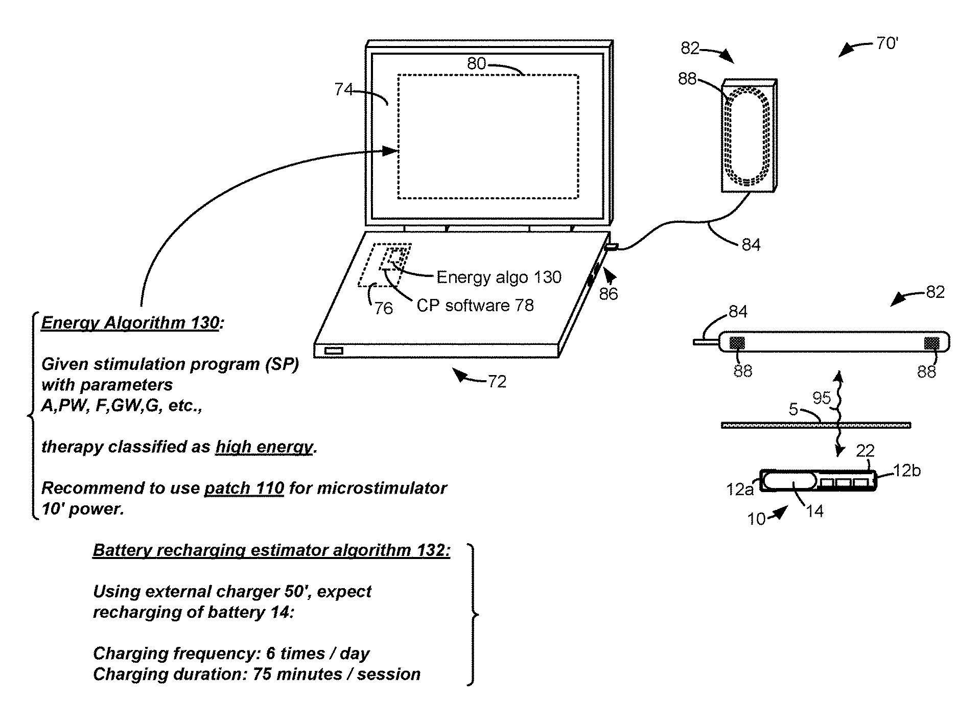
FIG. 2B shows an additional external device that supports the microstimulator 10. FIG. 2B shows a well-known clinician programr 70. It may be described in U.S. Patent Application Publication 2015.0360038. This is incorporated by reference in its entirety. A clinician programmer 70 can be used to monitor and control the microstimulator 10 of a patient in a clinical setting. The clinician programmer 70, for example, can be used to program the microstimulator 10, with the most effective stimulation program, after which the patient can modify the program using his external controller 30, as needed. You can also use the clinician programmer 70 to perform routine checks and adjust the stimulation program, or monitor the microstimulator 10.
The clinician programmer 70 usually includes a personal computer 72. This computer may be portable such as a tablet or laptop computer. The computer 72 contains a display 74 and a graphical user interface (80) that is rendered by clinician programr (CP), software 78 executed through control circuitry 76. The computer 72 may not have the ability to communicate with the implant directly, so the clinician programmer 70 may include a communication head (82), sometimes called a “wand”. The communication head82 contains an antenna coil 88 that functions in the same way as the coil 32 in external controller 30 and is capable of communicating via link 95 (e.g. by FSK) with the coil 22 in microstimulator. The communication head82 is connected to the port 86 of computer 72. This port may include a USB port, for example. The communication head 82 could also contain modulation or demodulation circuitry, but this is not shown.
A microstimulator like 10 can be used to provide neurostimulation at many places in the body, and for many other therapeutic purposes such as those mentioned above. The inventor points out that the battery 14 in the microstimulator 10, which is small and therefore has a low capacity, is also necessary. Battery 14 might have a capacity of 20mAh, for instance. A battery 14 with a capacity of 20 mAh may not be sufficient to power the microstimulator for long enough between charging sessions by the external charger 50. This invention addresses this issue by providing a system that provides external power differently to the microstimulator 10, depending on what therapy is being provided.
A microstimulator 10’s rechargeable battery 14 is small and has a relatively low capacity. Depending on the type of therapy that is being provided by the microstimulator 10, the battery 14 will need to be recharged frequently using the external charger 50. FIG. shows examples of various therapies. 3 consists of different types of stimulation pulses which pass through the patient’s tissue, 5 from electrode (12 a) to electrode (12 b).
The top row of pulses shows conventional stimulation therapy. In this case, pulses are issued at a frequency F1, with an amplitude of A and a pulse width of PW. Aa A biphasic pulse is common in a neurostimulator, although it is not necessary. It promotes charge recovery from any capacitances that may exist in the current path, I. The example shows that the amplitudes (Aa), Ab and pulse widths(PWa, Wb) are equal in the two pulse phases 99.a and 99.b. However, the opposite-polarity pulse 99.b can have different pulse widths and amplitudes, while still meeting the same charge as the first pulse phase 99.a. Biphasic pulses are a useful tool in neurostimulators.
The pulse frequency F1 in the top row may be less than 5 kHz, which is considered low frequency. The pulse widths PW can therefore be 200 microseconds or greater. High frequency stimulation is also promoted in neurostimulation arts. FIG. 3. This example shows that pulses, which are again illustrated as biphasic but are not necessarily necessary, are issued at higher frequencies F2. These frequencies may be greater than 5kHz and typically less than 1 Mhz. F2 can be higher than 10 kHz or lower than 150 kHz. High frequency stimulation can use pulse widths PW that are less than 200 microseconds. High frequency stimulation is said to provide pain relief in Spinal Cord Stimulator applications, for example, without inducing paresthesia. You can refer to the U.S. Patent Application Publication 2010,/0274312, for more information.
Depending on the patient?s therapeutic needs, high frequency pulses can be either free-running, as shown in the bottom row, or issued with periods of no stimulation between, as shown in the right hand side of the bottom rows. These groups of pulses can have a group width (GW), which may contain a plurality pulses. In one instance, the group widths could equal the pulse widths provided by low frequency therapies. These groups of pulses may emit a frequency G which can generally be equal to the pulse frequencies (F1) used in low frequency therapies.
It is not possible to determine which type of therapy (low frequency or high frequency; free running, or in groups) will be the most effective for a patient at the time microstimulator 10 is inserted. Microstimulator 10 should be able to emit stimulation pulses according any of these modes. The inventor recognizes that it is advantageous for microstimulator 10, to be programmeable to provide a wide range of therapies, such as those shown in FIG. 3. The therapy that is implemented in a microstimulator 10 to treat a patient has a significant impact on the power draw within the microstimulator 10. This has an effect on the rechargeable batteries 14.
![]()
Low frequency stimulation is generally low in energy and draws less power from the rechargeable batteries. There are many reasons low energies can result from low frequency therapies. The pulse widths PW can be smaller than the time (T1=1/F1) during which low frequency pulses are generated (i.e. the pulses have a lower duty cycle) or they may not change that often. The microstimulator 10 requires switching of circuitry to produce transitions in the pulses’ shape. As is well known, power draw is proportional to the rate of switching.

Click here to view the patent on Google Patents.