Invented by Aly E. Orady, Bret G. Stott, Tonal Systems Inc
Exercise machines, such as treadmills, ellipticals, and stationary bikes, have become a staple in both home and commercial gyms. They provide a convenient and effective way to stay fit and active. However, accidents and injuries related to exercise machines have also been on the rise. This has led to a growing concern for the safety of users, prompting manufacturers to invest in safety improvements.
One of the key areas of focus for exercise machine safety improvements is the prevention of accidents and injuries caused by user error. Many accidents occur due to improper use or lack of knowledge about the correct form and technique. Manufacturers are now incorporating features such as instructional videos, built-in sensors, and automatic adjustments to guide users and prevent injuries.
Another area of improvement is the design and construction of exercise machines. Manufacturers are investing in research and development to create machines that are more stable, durable, and resistant to wear and tear. This includes using high-quality materials, improving the structural integrity, and enhancing the overall stability of the machines. Additionally, ergonomic designs are being implemented to ensure proper body alignment and reduce the risk of strain or injury.
Furthermore, technology has played a significant role in improving exercise machine safety. Many machines now come equipped with advanced monitoring systems that track heart rate, blood pressure, and other vital signs. These systems can alert users and trainers if any abnormalities are detected, allowing for immediate intervention. Additionally, some machines have integrated safety features such as emergency stop buttons and automatic shut-off mechanisms to prevent accidents.
The market for exercise machine safety improvements is not limited to manufacturers alone. Fitness facilities and gyms are also investing in upgrading their equipment to ensure the safety of their members. This includes regular maintenance, inspections, and replacing outdated machines with newer, safer models. Gym owners understand the importance of providing a safe environment for their members and are willing to invest in the necessary upgrades.
In conclusion, the market for exercise machine safety improvements has witnessed significant growth in response to the increasing demand for exercise machines. Manufacturers are investing in research and development to enhance safety features, improve machine design, and incorporate advanced technology. Fitness facilities are also taking steps to ensure the safety of their members by upgrading their equipment. With these advancements, exercise machines are becoming safer and more user-friendly, allowing individuals to enjoy their workouts without the fear of accidents or injuries.


The Tonal Systems Inc invention works as follows
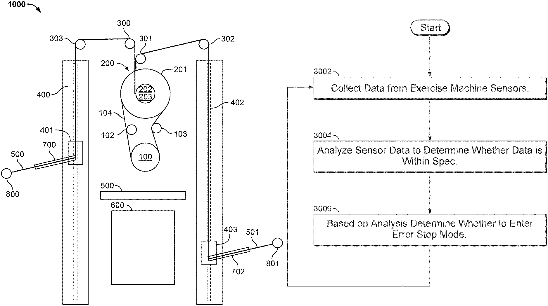
Data is collected by a sensor that monitors a tension-generating device on an exercise machine. The sensor data will be analyzed in order to determine if it is within the specification. If the sensor data does not meet the specifications, an error stop mode for the tension generator is entered.


Background for Exercise machine safety improvements
Strength training is also known as resistance training or lifting weights. It’s an important part of every exercise program. It helps to build muscle, burn fat and improve a variety of metabolic factors, including insulin sensitivity, lipid levels and elasticity. “Many users are looking for a safer and more effective method of strength training.
The invention may be implemented in many ways. It can be used as an apparatus, a process, a system, a composition, a product of computer programming, and/or a CPU, such as one that executes instructions stored on or provided by a memory connected to the processor. These implementations and any other form of the invention can be called techniques in this specification. The invention allows for the possibility of altering the order of steps in disclosed processes. A component, such as a processor and a memory, described as being capable of performing a task can be implemented either as a general component that is temporarily set up to perform the task at a particular time or as a specific component that was manufactured to do the task. The term “processor” is used herein. The term “processor” refers to any one or more devices, circuits and/or processing cores that are designed to process data such as computer program instruction.
Below is a detailed description of some embodiments of the invention, along with accompanying figures that illustrate its principles. Although the invention is described with these embodiments in mind, it is not limited to them. The claims limit the scope of the invention, and the invention includes many alternatives, modifications, and equivalents. The following description provides a detailed understanding of the invention. These details are given for example purposes only. The invention can be used according to the claims without any or all of these details. To be clear, the technical material related to the invention that is well-known has not been described in detail. This is done in order not to obscure the invention.
The majority of strength-training methods and/or equipment fall into one or more of the following categories.
While gravity is the primary source for tension or resistance, tension can also be achieved by using elastics such as rubber bands/resistance band as with THERABAND. Other methods include pneumatics and hydraulics. These systems are characterized by their own tension curve.
Electronic Resistance.
Patent application Ser. No. No. 20. 2017, which is incorporated by reference herein for all purposes. Electronic resistance can be generated by an electromagnetic field, an electronic motor, or a brushless direct current (BLDC) three-phase motor. The techniques discussed in the present application can be applied to any other traditional exercise machine without restriction, such as exercise machines that use pneumatic cylinders or springs.
Low Profile.
A strength-trainer using electricity to create tension/resistance can be smaller and lighter than conventional strength-training systems, such as a stack of weights, and therefore, it may be installed or mounted at more places, for example, the wall of a room in a residential house. Low-profile systems and components will be preferred for this type of strength trainer. Strength trainers that use electricity to create tension/resistance can also be made versatile through electronic or digital control. Software can be used to control tension with electronic control. Traditional systems, on the other hand, require that tension be manually/physically changed. In the case of weight stacks, a pin must be moved from one metal plate onto another by a user.
The digital strength trainer that uses electricity to create tension/resistance can also be versatile, as it has dynamic resistance. This allows tension/resistance to be changed almost instantly. Digital strength trainers can apply tension curves based on the position of the user and their range of movement. This includes both the phase and the position. The shape of the curves can be altered continuously or in response to an event. Tension may also be controlled in real-time based on internal and external variables, including phase and position.


FIG. “FIG. 1A is a diagram showing an embodiment of a machine for exercising. “The exercise machine includes:
a controller circuit (1004), which may include a processor, inverter, pulse-width-modulator, and/or a Variable Frequency Drive (VFD);
a motor (1006), such as a brushless DC three-phase motor driven by the control circuit;
A spool wrapped with a cable (1008) and coupled to it. The cable is connected to an actuator/handle (1010) so that the user can grip and pull. The spool is coupled to the motor (1006) either directly or via a shaft/belt/chain/gear mechanism. In this specification, the spool is also called a “hub”. ;
A filter (1002) to digitally control controller circuit (1004) based on information received from the cable (1008 and/or actuator (10010)
Optionally (not shown on FIG. 1A) A gearbox is placed between the motor and the spool. Gearboxes can multiply torque or friction, divide speed and/or split the power between multiple spools. A number of combinations of motors and gearboxes can be used without changing the fundamentals for digital strength training. “A cable-pulley system can be used instead of a motor, or a dual motor can be used instead of a transmission;
1A): “one or more sensors” 1A):
A position encoder, a sensor that measures the position of the motor (1010) or actuator (1010). Position encoders can include hall effect shaft encoders, grey-code encoders on motors/spools/cables (1008), accelerometers in actuators/handles (1010), optical sensors or position measurement sensors/methods integrated directly into motors (1006). In one embodiment, a low-resolution encoder is associated with a phase encoder that uses an optical encoder with a pattern of encoding. There are also other options which measure the back-EMF from the motor (1006) in order to calculate location.
a motor power sensors; a sensor that measures voltage and/or the current consumed by the motor (1006);
a user tension sensor; a torque/tension/strain sensor and/or gauge to measure how much tension/force is being applied to the actuator (1010) by the user. In one embodiment, the tension sensor is integrated into the cable (1008). A strain gauge can also be built into the motor mount that holds the motor (1006). The strain that is created by the user pulling on the actuator (1010) can be measured with a Wheatstone Bridge strain gauge. In another embodiment, a cable (1008) can be guided through a pulledey that is coupled to a cell of load. In another embodiment, the belt that connects the motor (1006) with cable spool (1008) or gearbox (1008) is guided through a pulledey coupled to a cell. In another embodiment, resistance generated by motor (1006) can be characterized according to voltage, current or frequency inputted into the motor.


In one embodiment, the three-phase brushless DC (1006) motor is used in conjunction with:


Click here to view the patent on Google Patents.