Invented by Robert Y. Jin, Mark Kent Sloan, Abbott Diabetes Care Inc
CGM systems consist of a small sensor that is inserted under the skin to measure glucose levels in the interstitial fluid. The sensor is connected to a transmitter that sends data to a receiver or smartphone app. Some CGM systems also include insulin pumps that can automatically adjust insulin doses based on glucose readings.
There are several methods of using CGM systems, depending on the specific device and individual needs. One common method is to wear the sensor continuously for several days or even weeks, with regular calibration using fingerstick blood glucose readings. This allows for a comprehensive view of glucose trends and patterns over time.
Another method is to use CGM intermittently, such as during periods of high physical activity or when fasting for religious or medical reasons. This can provide valuable insights into how the body responds to different situations and help prevent hypoglycemia or hyperglycemia.
CGM systems are particularly beneficial for people with type 1 diabetes, who require insulin therapy to survive. However, they can also be useful for people with type 2 diabetes who are on insulin or other medications that can cause hypoglycemia.
The market for CGM systems is expected to grow significantly in the coming years, driven by increasing prevalence of diabetes and advancements in technology. According to a report by MarketsandMarkets, the global CGM market is projected to reach $10.4 billion by 2024, with a compound annual growth rate of 15.8%.
Several companies are currently leading the way in CGM technology, including Dexcom, Abbott, and Medtronic. These companies are constantly innovating and improving their devices to provide more accurate and user-friendly options for people with diabetes.
In conclusion, CGM systems are a game-changer for people with diabetes, providing real-time data and insights that can help improve blood sugar management and overall health. As the market for these devices continues to grow, we can expect to see even more advancements in technology and methods of use.
The Abbott Diabetes Care Inc invention works as follows
A continuous glucose monitoring system that includes a sensor capable of detecting one or several glucose levels and a transmitter operatively connected to the sensor. The transmitter is configured to receive and transmit signals corresponding the detected glucose levels. A receiver operatively connected to the transmitter is designed to receive signals corresponding the detected glucose levels. Methods and specifications for such a system are disclosed. One aspect of the transmitter is capable of transmitting a current and at most one previous data points, the current and at least one past data points, respectively, corresponding to the detected glucose level.
Background for Continuous glucose monitoring system, and methods of using
The present invention is related to continuous glucose monitoring systems. The present invention is a continuous glucose monitoring system that detects glucose levels in real time and transmits the information to data processing devices to monitor, diagnose, and analyze the glucose.
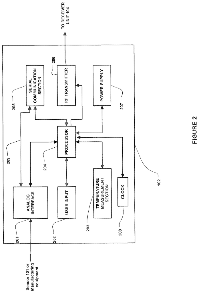
A continuous glucose monitoring system according to one embodiment of the invention comprises a sensor that detects one or several glucose levels. The transmitter is operatively coupled with the sensor and configured to receive the detected glucose levels. The transmitter is further configured transmit signals corresponding the detected glucose levels. A receiver operatively connected to the transmitter can receive signals corresponding the transmitted glucose levels.
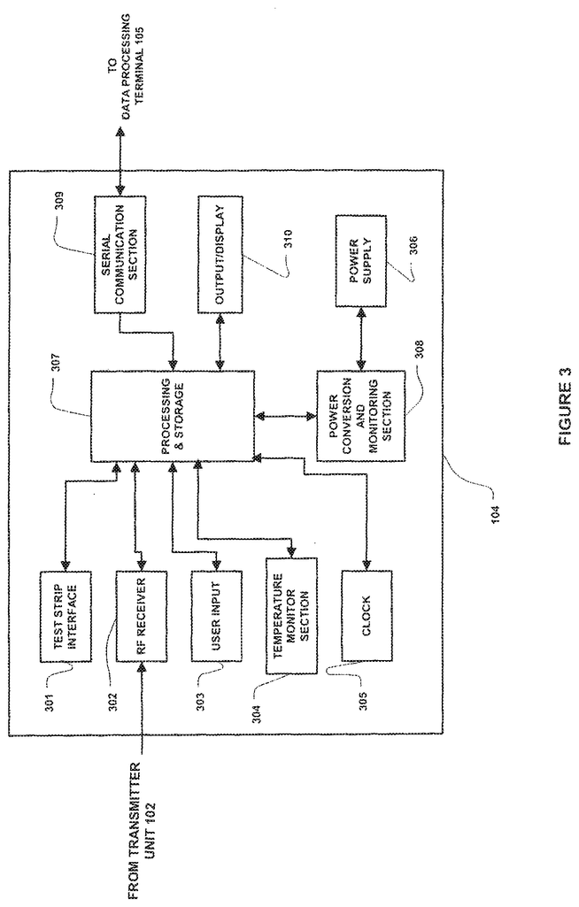
The receiver can be operatively connected to the transmitter using an RF communication link and further configured to decode encoded signals received by the transmitter.
In one embodiment, the transmitter could periodically transmit a glucose level detected by the sensor to the receiver over the RF communication link. One embodiment may allow the transmitter to be programmed to sample four times per second in order to get 240 data points per minute. The transmitter can also transmit one data point (e.g. an average of the 240 data points per minute) per minute to receiver.
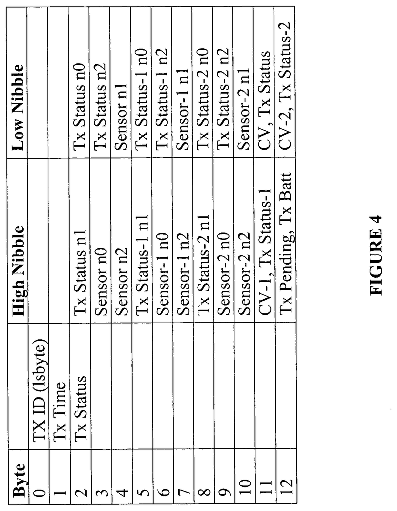
The transmitter can be configured to send three data points per minute to a receiver. The first data point represents the current sampled data and the two remaining data points represent the two immediately preceding data points sent to the receiver. If the receiver fails to receive the sampled data from transmitter, then the receiver will receive the next data transmission. This allows for missed data points to be determined even if there is a problem with the transmitter or receiver’s RF data link.
The transmitter can be programmed to encode one or more glucose levels detected by the sensor and transmit these encoded signals to receiver. The transmitter may transmit encoded signals to receiver at one data point per minute in one embodiment. The transmitter can transmit both the current data point as well as the at least one of the previous data points to the receiver in one transmission per minute. One aspect of this is that the current data point could correspond to a glucose level. The at least one previous point may contain at least two data points that correspond respectively to at most two consecutive glucose levels. In other words, the data point corresponding to the current glucose level may be the one immediately preceding it.
A further embodiment may include an output unit that can send out the transmitted signals, which correspond to one or more glucose levels. An output unit could include a display unit that displays data for the one or more glucose levels. The display unit can include an LCD, cathode-ray tube, or plasma display.
The displayed data could include an alphanumeric representation that corresponds to one or several glucose levels, a graphic representation of one or multiple glucose levels, or a three-dimensional representation. The display unit can be set up to display data that corresponds to one or more glucose levels in real-time.
Further, an output unit might include a speaker to output an audio signal that corresponds with one or more glucose levels.
In another embodiment, the receiver could be configured to store identification information that corresponds to the transmitter.
The receiver can also be configured to use a time-hopping technique for synchronizing with transmitters. The receiver could also be programmed to sync with the transmitter according to the signal strength detected by the transmitter. This is possible if the transmitter’s signal strength exceeds a predetermined threshold level.
The transmitter may be enclosed in a substantially waterproof housing in order to maintain operation even when in direct contact with water.
The transmitter can also be equipped with a disable switch that allows the user temporarily to disable data transmission to the receiver, in case the user needs to disable electronic devices (e.g., while onboard an airplane). Another embodiment of the transmitter can be set up to operate in a third state, such as the Class B radiated emission standard. This allows for limited operation aboard an airplane while still complying to Federal Aviation Administration (FAA). The disable switch can also be used to toggle between different operating modes, such as fully functional transmission mode or post-manufacture sleeping mode. This allows the transmitter to be used for longer periods of time by efficiently managing its power consumption.
The transmitter can be set up to send data to the receiver using predetermined data packets. These data packets may include Reed Solomon encoding and will be transmitted over the RF communication link. A further aspect of this invention is that the RF communication link between transmitter and receiver of continuous glucose monitoring system can be made using an inexpensive, off-the-shelf remote keyless entry (RKE), chip set.
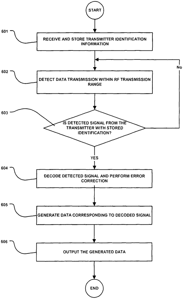
The receiver of an additional embodiment can be configured to decode, correct, and detect errors (using, for instance, forward error correction) on encoded data packets received by the transmitter. This will minimize transmission errors such error as transmitter stabilization errors or preamble bit errors due to noise. To identify and sync with the appropriate transmitter for data transmission, the receiver can also perform synchronized time hop procedures with it.
The receiver may also include a graphical user interface (GUI), which displays the data received from transmitter to the user. A liquid crystal display (LCD), with backlighting, may be included in the GUI. This allows for visual display even in dark environments. An output unit may be included in the receiver to generate and send audible alerts to the user. The receiver can also be placed in vibration mode, which vibrates the receiver to alert the user.
A further aspect is that the receiver can be configured to display glucose levels received on a display section of its receiver in real-time or upon user request. It may also provide visual (and/or audio) notification to the user about the glucose levels being monitored. The receiver can be configured to identify the transmitter it is to receive data over the RF data line. This is done by first storing the identification data of the transmitter and then performing a time hopping process to isolate the data transmissions from the transmitter corresponding with the stored identification information. The receiver can also be programmed to identify the transmitter by analyzing the signal strength from the transmitter. This is based on a predetermined threshold level.
A method according to one embodiment of the invention comprises the steps of receiving identification information correspondingly to a transmitter, detecting data in a predetermined range of RF transmission, determining if the transmitted data is from the transmitter, decoding and generating an out signal correspondingly to the decoded data.
In one embodiment, the step to determine whether the detected data transmission has been transmitted from the transmitter can be based upon the received identification information. Another embodiment may use the received identification information to determine whether the transmitted data is detected from the transmitter. This step could be determined based on the signal strength or duration of the data detected within the predetermined range of radio frequency transmission.
In another embodiment, the step decoding may also include performing error correction on decoded data.” The step of decoding could also include the step to perform Reed-Solomon decoding of the detected data.
The present invention is a continuous glucose monitoring system which can be used in a simple and compact manner to minimize interference to the user’s daily life. The continuous glucose monitoring system can be made water-resistant to allow the user to swim, bathe, and enjoy other water-related activities while it is being used. The components of the monitoring system, including the transmitter, can be configured to operate in different modes to allow power savings and increase post-manufacture shelf lives.
Click here to view the patent on Google Patents.


