Invented by Buddy Aswin, US Department of Navy
One of the key components of a machine vision system is the camera. Cameras used in machine vision systems are typically designed to capture high-resolution images with minimal distortion or noise. They may be specialized for specific applications, such as infrared or ultraviolet imaging, or may be designed to work in challenging environments, such as those with low light or high vibration.
Another important component of a machine vision system is the software used to analyze the images captured by the camera. This software may be designed to perform a variety of tasks, such as identifying defects in manufactured products, tracking the movement of objects, or recognizing faces or other patterns. Machine learning algorithms are often used to improve the accuracy and efficiency of these analyses.
In addition to cameras and software, there are a variety of other apparatuses, methods, and devices that support machine vision systems. These may include lighting systems designed to provide consistent illumination for imaging, lenses and filters to modify the properties of the captured images, and mounting hardware to secure cameras and other components in place.
The market for these components is driven by a variety of factors, including the increasing demand for automation and the growing use of machine vision systems in a wide range of industries. As these systems become more sophisticated and capable, the demand for high-quality components will continue to grow.
One of the key trends in the market for machine vision components is the increasing use of artificial intelligence and machine learning algorithms. These technologies are being used to improve the accuracy and efficiency of image analysis, and to enable new applications and use cases for machine vision systems. As the capabilities of these systems continue to evolve, the demand for specialized components and devices will continue to grow.
Overall, the market for apparatuses, methods, and devices for machine vision systems is a dynamic and rapidly evolving space. As new technologies and applications emerge, the demand for high-quality components will continue to grow, creating new opportunities for innovation and growth in the industry.


The US Department of Navy invention works as follows
Machine vision methods/systems and related applications systems/methods are available that include steps/control sections such as capturing multiple images from at minimum two cameras with overlapping fields of view and camera settings, first- and second-category depth estimation (DEM) modules (DEM that generates a first (z) and second (NN) depth estimates (z), DE neural trainer (NN) trigger systems, a camera setting module and an application that uses outputs of the first or second categories DEM. The first category DEM features matching, structure, motion (SFM), depth form defocus (DFD), relative blur estimations (RBE), generators, DE neural network trainer (NN) trigger system, a camera setting module, and an application that uses outputs from the first or second category DEM. The second DEM contains a NN DE trainer/use-system. A reinforcement learning camera setting selection method is also used.


Background for Apparatuses, methods and devices for machine vision system
The present invention is related to machine vision systems that create models from two-dimensional images taken from multiple angles and multiple camera settings. Camera setting includes system states (e.g. machine vision systems that can be used to create models based on two-dimensional images from multiple perspectives, multiple camera settings (camera setting includes system states (e.g. vehicle speed, direction), and active and passive range sensors for a variety applications. Machine vision systems are available for many machine vision applications.
Common imaging systems do not have to be able to offer three-dimensional (3D) imaging capabilities or range finding capability. A collection of 2D images can still be used to reconstruct a 3D scene or range. Structure from Motion (SFM) requires the camera to move in a translational direction. Depth from Defocus algorithm (DFD), however, restricts camera movement.
Research and development were undertaken to address the limitations of each method by looking at how limitations and advantages associated with current approaches to using 2D imagery to create 3D models within the 2D image. This included modifications, combinations and additions to DFD and SFM approaches. Particular efforts were made to compare the precision and accuracy of DFD, SFM and to find an approach to creating embodiments that included modifications and combinations of both useful aspects of DFD or SFM while addressing or eliminating mutually exclusive limitations.
For various purposes, there have been a variety of SFM, stereo vision and DFD algorithms. One example is the 8 Points Algorithm. It was described in Hartley R. I. Zisserman A.,?Multiple View Geometry In Computer Vision?, Cambridge University Press ISBN: 0521540518. This model or description of translation and rotational movements of a camera using a linear transform function to determine camera location and 3D locations. However, it can make errors in different failure modes, such as when there is a small distance between them. Although translation and rotation can be described as a system involving symbolic polynomials, it still relies on a pre-existing point match which produces errors. It also requires significant computing power that is not practical for many applications. Simultaneous Localization and Mapping (SLAM), a real-time 3D estimation technique, relies on parallel processing. This is because it uses more expensive or more power-consuming resources to provide the computing power. Two pictures must be taken from the same camera angle and location as DFD techniques in their early days. Additionally, DFD methods are sensitive to image scaling and image shifting, which are common in real-world application image recording processes.
Existing SFM algorithms won’t work under certain conditions (e.g. failure modes or conditions), such as pure rotation or a combination image point locations and camera movements. SFM algorithms and systems can cause many failures or errors in imaging systems such as forward-facing cameras on vehicles or security cameras that rotate. SFM techniques can make it difficult to estimate depth or determine z coordinates for feature pairs x,y coordinates in multiple images. This is because distances between the cameras and structures within the camera’s field of view are too small. Existing SFM methods also have problems when attempting to match feature pixels between images from different perspectives. These feature-matched pixels pixel x and y coordinates can be used later to perform triangulation steps. These errors are at least partially due to the way traditional SFM systems that use feature matching use 2D images to deduce difference(s), in two-dimensional coordinates that are small, so they end up measuring mostly noise during the feature matching step. Traditional DFD methods assume that cameras will remain in the same place, and cameras’ settings change. This creates camera motion error. It is also difficult to estimate relative defocus blur with cameras in motion.
Real-time applications based on the existing SFM or DFD methods are difficult to use because they require significant computational resources. Although passive depth sensing with a single monocular photo can be done in real-time, it still requires significant resources. There are also inherent limitations and tradeoffs that must be made. Machine learning algorithms for monocular depth estimation are typically trained offline using an active range finder and several 2D images. The trained algorithm then determines depth in real-time.
Accordingly, current systems or technology have a variety disadvantages when used in applications like range finding, 3D mapping, and machine vision. when different techniques are used in various failure conditions. Therefore, it was necessary to improve the art to address different disadvantages and allow for various applications.
Improved combinations SFM, DFD and monocular depth estimation processes as well machine learning systems and apparatuses, including imager systems, allow a vehicle to be equipped with two-dimensional cameras mounted relatively close together to explore the surrounding environment and mitigate measurement error using multiple camera settings. This allows the vehicle to use multiple camera settings without a pretrained machine learning system and is able to operate both with and without movement.
An embodiment of the invention may include live training of a machine learning algorithm. This can be done using output from DFD and SFM measurement, as well as a series 2D images that were acquired live (as a vehicle moves in an environment), and with computer generated data and images. The machine learning can also be trained parallelly and the newly trained algorithm can then be used to predict depth. Machine learning can also be used to select the best camera settings for specific environments, weather conditions, object distances, and other characteristics. This is because passive depth estimation calculations are dependent on the camera settings.
Also machine learning systems require a lot of learning data. Even if they are pre-trained, they will not be able adapt to different environments or operate in them. The invention allows an exemplary system to quickly adapt to new environments that are not covered in its training data. Many systems only use one camera, or two cameras that are close together and don’t move. These systems need to be able to perform complex tasks like range finding and 3D mapping with greater accuracy. However, existing systems and methods are not able or willing to accommodate these needs.


In some cases where the structure from motion is not stable, camera and depth location can still be recovered by integrating and modifying DFD and SFM. The algorithms that combine multiple depth cues from monocular cameras focus mainly on triangulation of 3D scene positions from pre-calibrated camera positions.
In at most some embodiments of this invention, a 3D reconstruction is performed from near-focused and far-focused 2D synthetic images without knowing the camera locations. To mitigate the limitations and errors of each individual SFM/DFD algorithm, depth cues are obtained from DFD and SFM machine directions or logic sequences. This article discusses or provides several DFD and SFM approaches, as well as state-of-the-art techniques. We also provide a robust relative blur estimation algorithm as well as a method to combine DFD and FFM cues from multiple photos.
An exemplary point-cloud SFM/DFD fusion method improves the robustness or capability of depth measurement in situations when multiple cameras are located at a small, but significant distance from each other. This helps to mitigate or address prior art problems in feature matching (e.g. is inconsistent). The invention can be used in situations where multiple generic SFM or DFD software systems fail to produce 3D reconstructions. Exemplary systems or methods for improving point cloud SFM/DFD fusion were able to produce a 3D reconstruction of structures from scenes captured by exemplary systems.
Passive rangefinder and 3D mapping applications. In general, exemplary control algorithms, machine instructions, or algorithms are used to combine passive 3D cues from 2D photos taken at different sensor locations (e.g. SFM) to create 3D depth maps using 2D images. This is done by symbolic-numeric approach, which provides robustness against and the ability to operate in degenerate environments that traditional techniques were not able to.
In particular, embodiments include an algorithm for estimating relative blur between elements from at least two sets or sets of images taken in different locations and/or sensor settings. These are robust against multiview image transformation and multiview/stereo correspondence mistakes. Machine-readable instructions and control instructions can be included in embodiments. These include an algorithm for measuring relative blur between 2D images taken at different angles and camera settings, an algorithm that combines active depth sensor with passive 3D depth cues (DFD), and an algorithm to calculate 3D information from a single monocular image using statistical and machine learning techniques. This can be trained with live or computer generated images, and can allow for adjustable processing speed. A machine learning algorithm can also be used to determine the best camera settings to achieve 3D depth estimation
Additional uses. “Additional uses” can also be made of the exemplary embodiments. These include potential new applications, including 3D imaging. The algorithm can estimate relative blur between images and can generate a synthetic aperture sensor. Based on the scene and sensors that create blurred images, the algorithm can also model the physical mechanism. The blur formation model and relative blur information may provide information about camera settings or scene characteristics.
An example algorithm was tested using a thin lens model. However, other models can be used for hardware (e.g. fish eye lenses). Integration of the exemplary algorithm with other computer-vision algorithms is possible. The estimation of the relative blur between objects and scenes in 2D pictures as well as 3D maps can be used in super resolution imaging algorithms, occlusion elimination, light field camera motion blur estimation, photo de-blurring and image registration. It can also be used as an initial 3D scene estimation in an iterative 3D estimation method. You can use examples to extract camera information from 2D photos, such as camera calibration, camera pose and sensor vibration correction. Auto focus can also be achieved using relative blur estimation. Exemplary blur estimation algorithms provide robustness against image transforms, transformation-induced errors, and hand shaking that can occur when images are taken using a hand-held digital camera. 3D imaging can also be used for target tracking, triangulation (e.g. With Kalman filter, passive range finder, and fire control system. An additional application could include the use of gesture recognition system interfaces. SFM can also be used to create 3D environments from 2D images. This can be useful for creating visual effects in movies and virtual and augmented reality applications. Embodiments that incorporate exemplary methods for 3D imaging microscopic objects with microscopes (including electronic and biological samples), and for applications in Astronomy with telescopes are another option. Examples can be used for 3D scanning, object recognition, manufacturing, inspection of products and counterfeit detection, as well as structural and vehicle inspections. The use of embodiments can also be applied to mitigating atmospheric change that may also produce relative blur information that can then be used for depth measurement. If depth of an object can be known, the relative blur can provide information about scintillation weather and atmospheric conditions (e.g. fog, turbulence, etc.). Relative blur data may be generated by atmospheric changes. These can also be modelled and used to measure depth. You can also use the exemplary designs with consumer cameras or medical tools (e.g. Embodiments can also be used with consumer cameras or medical tools (e.g., otoscopes, endoscopes), where exemplary designs and methods can be applied for 3D measurement or other characterizations of bumps. Furthermore, exemplary methods are also available for vehicle navigation, sensor and vehicle pose estimation, and visual odometry (e.g. measuring the position of a vehicle using visual cues). The invention can be modified to measure the movements of objects within the image by using knowledge of camera movement.
The present invention has additional features and benefits that will be apparent to those who are skilled in the art. The following description of an illustrative embodiment illustrates the best way to carry out the invention as it is currently perceived.
The embodiments of this invention are not meant to be exhaustive nor to limit the invention to the specific forms disclosed. The embodiments described herein are intended to allow one skilled in the art practice the invention.
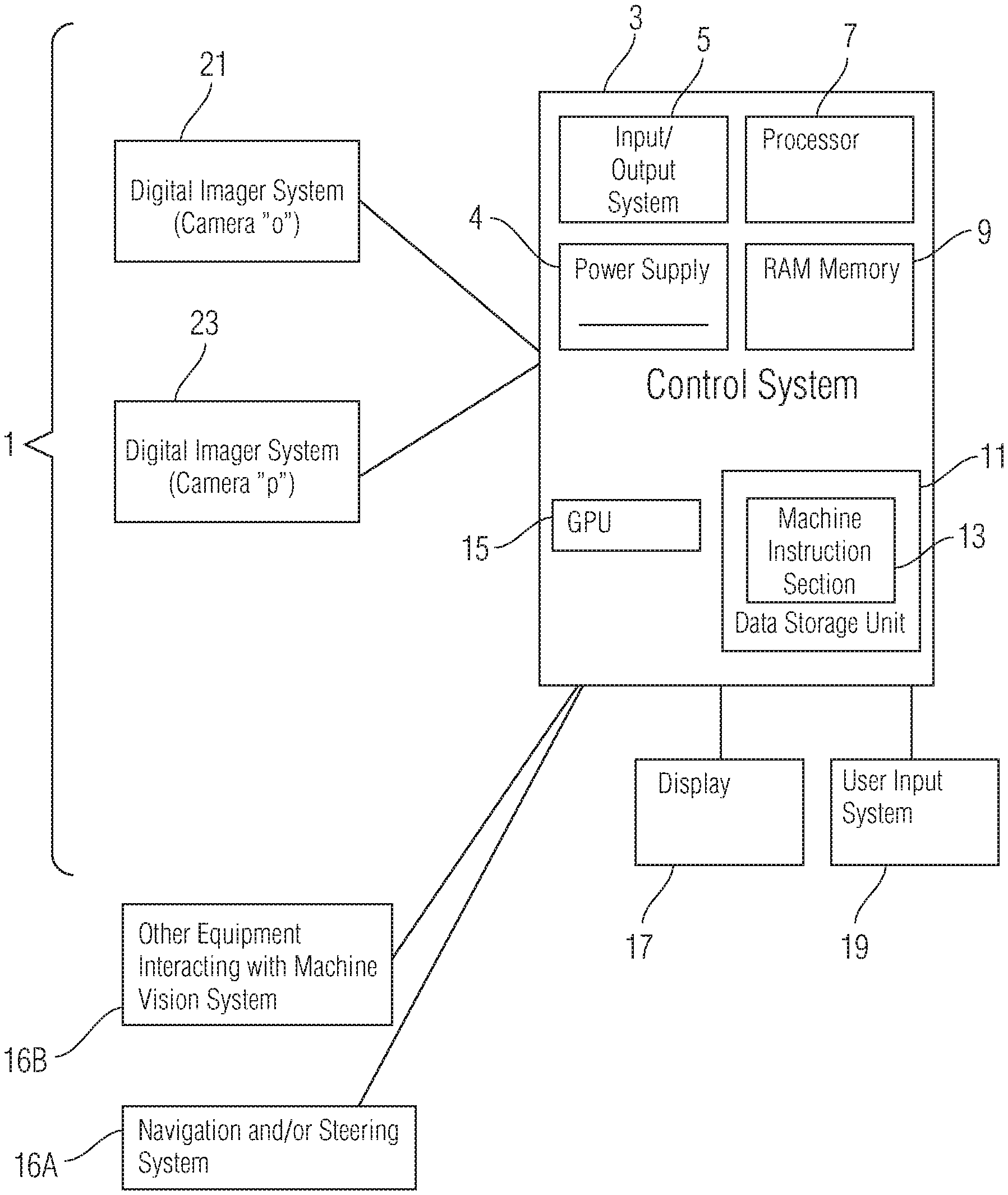
Referring first to FIG. FIG. 1 illustrates an exemplary hardware architecture according to one embodiment of the invention. It runs exemplary machine instructions and control logic, including a section for 3D depth estimation. Particularly, FIG. FIG. 1 illustrates an exemplary machine vision systems 1 that includes a computer or control, 3, input/output system 4, processor 7, random access memory 9 and data storage unit 11. The machine instructions (or alternatively control logic) are shown in the following. 13 are stored on the data storage area 11, graphical processing units (GPU), 15, and user input systems 19 (e.g. for some embodiments this might include a computer or control system 3, power supply 4, input/output system 5, processor 7, random access memory (RAM) 9, and data storage unit 11. Machine instructions or alternatively control logic (hereinafter referred to as “machine instruction section?”). An optional display 17 is used with applications such that described with regard to the input method 19. It can be fixed or moved to different settings and an overlapping field of target structures 2). Control system 3 regulates the timing of digital imager systems 21 and 23. These systems are synchronized by control section 3 to take two images simultaneously or substantially simultaneously. The digital imager system 21, 23 may need to be modified in cases where distant objects or structures are visible.


Although the invention allows for one camera, modifications to the invention are required. A single camera that moves in a static environment can be used to create a map of or a 3D model for static objects (e.g. buildings, trees, mountains, street signs or other fixed objects). Additional processing elements would be required to filter out elements of the non-static environment that are moving. One camera embodiment can produce multiple images, but it also has the option to use a beam splitter in order to create two images at once.


Click here to view the patent on Google Patents.