Invented by Herrmann; Adam, Kelly; Anthony, O’Keeffe; Conor, Menchon Enrich; Ricard, Kurahashi; Peter, Whitcombe; Amy, Krishnamurthy; Sundar, Dasalukunte; Deepak
In this article, we explore a patent application for a self-calibrating optical transceiver. We break down its background, its place in the current market, the scientific thinking and prior approaches that led to it, and the heart of the invention itself. Our goal is to give you a simple, clear, and actionable understanding of a technology that could change how the world connects through fiber and satellite links.


Background and Market Context
To understand why this new self-calibrating transceiver matters, it helps to look at how the world is changing. More people want fast, reliable internet connections. Companies want to send more data over longer distances, and they want to do it faster. The growth of cloud computing, streaming videos, and smart devices means we all need more data – and we need it to travel quickly, no matter where we are.
Fiber optic cables have long been the backbone of the internet, carrying information as light signals across oceans and continents. Recently, there’s also been a big push to use lasers and optical signals to connect satellites in space. These are called Low Earth Orbit (LEO) satellites. Companies like Amazon, SpaceX (Starlink), and OneWeb are putting thousands of these satellites into orbit to create global internet coverage. These satellites talk to each other and to the ground using beams of light, not radio waves, because optical signals carry more data and can travel farther with less interference.

But sending data as light is not simple. The systems that turn digital information into light (and back again) are complex. These systems are called coherent optical transceivers. They use many tiny parts like modulators, lasers, and photodetectors, all working together to send and receive signals. The challenge is that these parts are never perfect. Over time, or when they get hot or cold, their performance can drift. That means the signals can get fuzzy or distorted, causing errors and slowing down the connection.
Until now, fixing these imperfections has been hard. Traditional transceivers require careful setup and regular adjustment using expensive test equipment. In space, or across undersea cables, that kind of maintenance is not practical. The world needs transceivers that can check themselves and adjust on their own, without stopping the flow of data or sending out a technician. That’s exactly what this new patent aims to deliver: a transceiver that calibrates itself, keeping the signal clear and strong no matter where it is or what conditions it faces.
Scientific Rationale and Prior Art
Understanding the science behind this invention means looking at how optical transceivers have worked until now, and where they’ve fallen short. At the center of these systems are two basic tasks: turning digital signals into light, and turning light back into digital signals. This is done using digital-to-analog converters (DACs) to create electrical signals, modulators to turn those signals into light, and photodetectors with analog-to-digital converters (ADCs) to turn the received light back into data.
In a perfect world, every part of this process would work smoothly. But in real life, imperfections sneak in. For example, at very high frequencies, electrical signals can lose strength. Some parts of the system might react faster or slower than others, causing parts of the signal to arrive at different times (a problem called group delay). These issues show up as “droop” – where certain parts of the signal are weaker or out of phase, and the whole message becomes less clear.


To fix this, engineers use special filters—mathematical tools that can shape the signal and correct for droop. But these filters need to know exactly what the imperfections are, and that can change over time or as the system heats up. The usual way to find these imperfections is to send test signals through the system, measure what comes out, and then run calculations to figure out how to adjust the filters. That requires expensive equipment and skilled technicians, making it hard to do in the field or in space.
Some systems have tried to build in “self-test” features. But they often only check part of the system, or they can’t separate the imperfections of each part (like the transmitter vs. the receiver). They may also not work in real time, or not cover both the “I” (in-phase) and “Q” (quadrature) components of the signal, which are two key parts for sending complex data using light. When you mix in the added complexity of dual-polarization systems (using X and Y polarizations to double the data rate), the challenge gets even bigger. No simple, all-in-one, self-calibrating solution has existed—until now.
This new patent builds on decades of research in signal processing, digital filtering, and optical communications. It draws from the idea of using a “comb” test signal—a special waveform made up of many frequencies at once. By sending this comb through all parts of the system, and then carefully measuring the result, it’s possible to work backwards and find out exactly how each part is behaving. Solving sets of equations based on these measurements lets the system create the perfect filter to fix any droop or distortion, all on its own.
Invention Description and Key Innovations
This patent describes a self-calibrating transceiver that can check and fix itself automatically. It combines digital and optical technology in a way that allows it to measure its own performance, figure out what has gone wrong, and tune itself back to peak performance—all without outside help. Let’s break down the important parts and see how they work together.

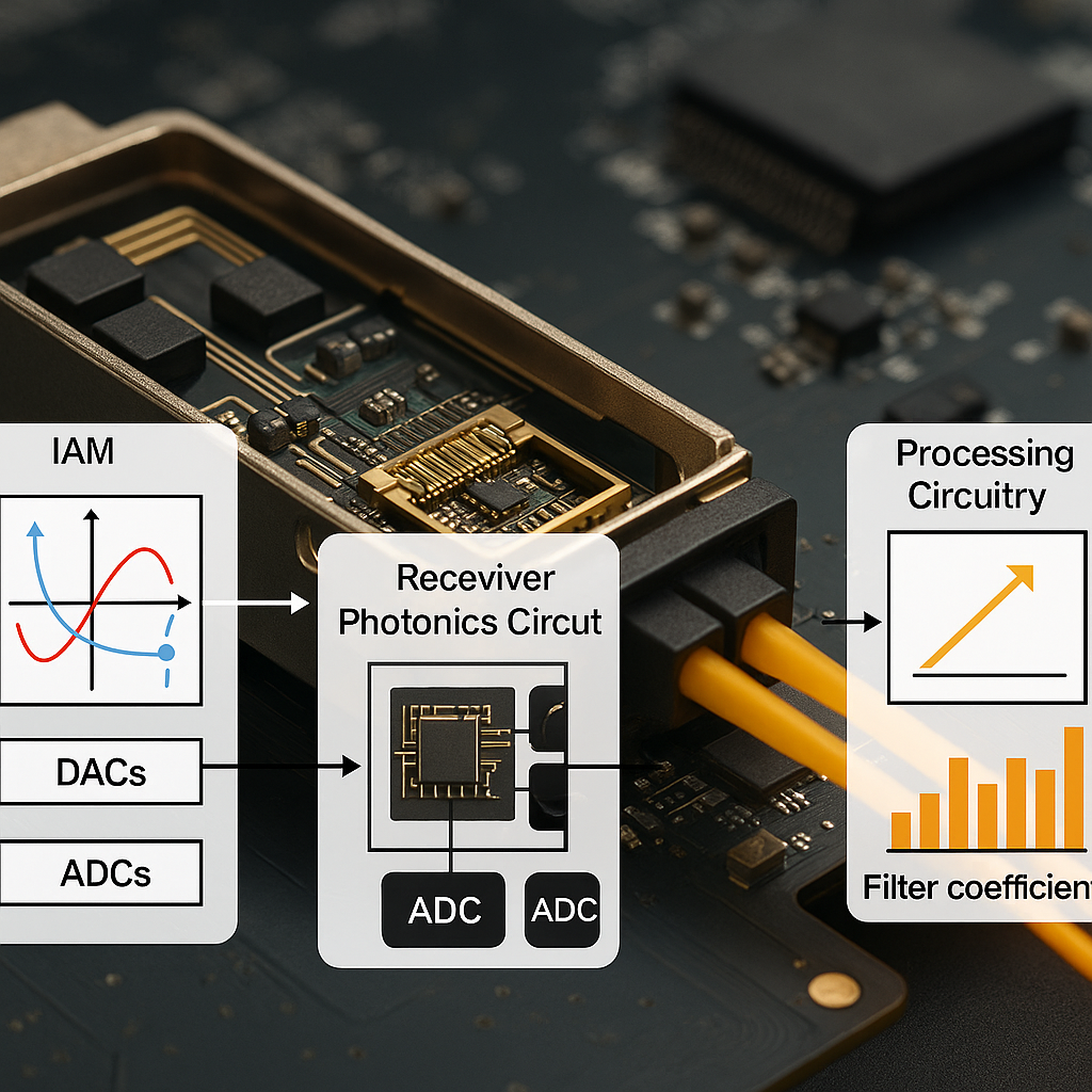
At the heart of the invention is a special calibration process. The system uses a set of digital-to-analog converters (DACs) to create a calibration test signal called a “comb waveform.” This signal is rich in many frequencies, like a musical chord made up of many notes. The comb waveform is sent through the optical modulator, where it’s turned into light signals with both I (in-phase) and Q (quadrature) components. These light signals travel through the optical path—just like real data would.
On the receiving end, the light signals are picked up by a receiver photonics circuit. This circuit turns the light back into electrical signals, which are then sampled and digitized by analog-to-digital converters (ADCs). The result is a digital record of what the calibration comb looked like after passing through the system.
Here’s where the magic happens: processing circuitry takes the digital record and compares it to the original comb waveform. By looking at changes in both the strength (magnitude) and the timing (phase) of each frequency in the comb, the system can see exactly how every part of the transceiver is behaving. This includes both the transmitter and receiver, as well as both polarizations (X and Y) if used. Because the system sends the comb through different path combinations, it can untangle the “droop” caused by each part separately. It does this by solving sets of equations for each frequency and each path.
Once it knows where the problems are, the system creates a set of filter coefficients. These are numbers that tell digital filters inside the transceiver how to fix the signal. The filters use these coefficients to shape the real data as it flows through, removing droop and keeping the signal clean and strong. The calibration can be repeated as often as needed, so the transceiver can adapt to changes in temperature, aging, or other factors that might affect performance.
There are several key innovations here:
– The transceiver can calibrate all parts of the signal path, including both transmitter and receiver, and both polarizations.
– It uses a comb waveform to test many frequencies at once, making the process fast and thorough.
– The system automatically solves for the best filter settings, no outside equipment needed.
– Calibration can be triggered through a software interface, making it easy to automate.
– The process works in real environments—on Earth or in space, in fiber or free-space optics.
The patent also describes how the system uses special hardware like 3 dB hybrid couplers and pairs of photodiodes to make sure the received signals are measured accurately. Fast Fourier Transforms (FFT) are used in the digital processing stage to quickly analyze the frequency response. The end result is a fully self-correcting transceiver that can keep working at its best, without human intervention.
This invention can be used in many places: fiber optic networks under the ocean or across cities, satellite-to-satellite laser links, and even future free-space optical systems that connect planes, drones, or ground stations. By making calibration automatic, it cuts costs, boosts reliability, and opens the door for faster, more robust global communications.
Conclusion
This patent for a self-calibrating optical transceiver marks a big step forward for global communications. By building in the ability to measure, analyze, and correct its own signal path, the technology ensures data stays clear and fast, no matter where or how it’s sent. The use of comb calibration waveforms, automatic filter tuning, and smart hardware integration all bring new levels of performance and reliability to the world of fiber and satellite links. As the demand for data keeps growing, advances like this will form the foundation of the networks that connect our world.
Click here https://ppubs.uspto.gov/pubwebapp/ and search 20250219735.